Back to Study material
BEE

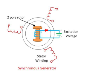
UNIT 5Single Phase Transformers Q1) Explain three phase synchronous generators?A1)The synchronous generator or alternator is an electrical machine that converts the mechanical power from a prime mover into an AC electrical power at a certain voltage and frequency. The synchronous motor always runs at a constant speed called synchronous speed.
  • The synchronous generator works on the principle of Faraday laws of electromagnetic induction.
  • The electromagnetic induction states that electromotive force induced in the armature coil if it is rotating in the uniform magnetic field.
  • The EMF will also be generated if the field rotates and the conductor becomes stationary.
  • Thus, the relative motion between the conductor and the field induces the EMF in the conductor. The wave shape of the induces voltage always a sinusoidal curve.
  •  The rotor and stator are the rotating and the stationary part of the synchronous generator. They are the power generating components of the synchronous generator. The rotor has the field pole, and the stator consists the armature conductor. The relative motion between the rotor and the stator induces the voltage between the conductor.

      
  • The three-phase synchronous generators have many advantages in generation, transmission and distribution.
  • The large synchronous generators use in the nuclear, thermal and hydropower system for generating the voltages.
  • The synchronous generator with 100MVA power rating uses in the generating station. The 500MVA power rating transformer use in the super thermal power stations.
  • The synchronous generators are the primary source of the electrical power. For the heavy power generation, the stator of the synchronous generator design for voltage ratings between 6.6 kV to 33 kV.
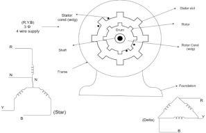
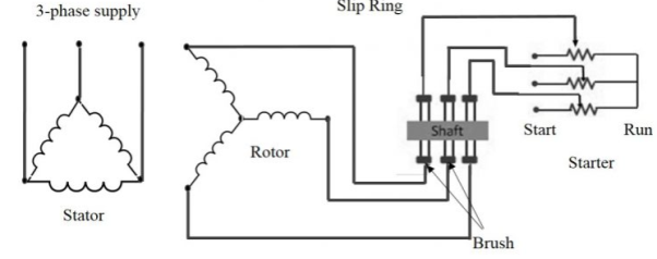
  •  Q2) Explain three phase induction motor?A2)Consider- 3Ф slip ring I.M Cut section diagram: -


     The induction motor has following important parts: -
  • Stator: - it is the stationary part of induction motor and it is one of important part in induction motor.
  • Rotor: - the rotor is the rotating part of induction motor which consists of rotor wdg.
  • Stator winding: - this wdg. Is mounted on devastator and it generates the RMF i.e. rotating magnetic field.
  • Rotor winding: - rotor winding is used to rotate the shaft of motor. This wdgis provided on rotor
  • Frame: - it provides the mechanical support to the motor. It is the outer covering of motor. It protects the internal parts of motor from damage.
  • Shaft: - shaft is used to connect to the load and four rotations.
  • Slip rings and brushes: - slip rings are mounted on the shaft which is connected with brushes from which connection is given to the external resistant or rheostat
  • Cooling fan: - this is provided for cooling purpose of motor and its internal parts.
  •  Q3) Explain the operation of induction motor?A3) 

      
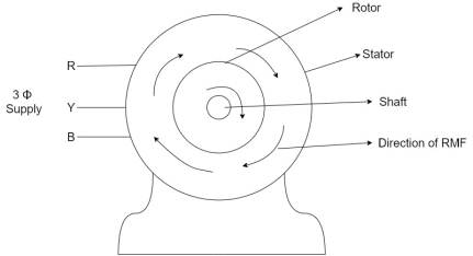
  • When the 3Ф A.C supply is connected across the stator of induction motor, the current starts flowing through the stator wdg. i.e the stator condition.
  • Due to this current of flux (Ф) is established in the stator wdg. This flux (Ф) is alternating (changing) in nature. Thus this flux links with the rotor also, and a a Rotating Magnetic Field (RMF) is produced.
  • This flux (Ф) induces in the rotor also. The RMF is produced in the air gap between stator and rotor.
  • The rotor is rotating part which is till stationary, show the rotating magnetic field is cut by stationary rotor and an EMF is induced in the rotor winding. According to faraday's law of EMI the rotor EMF gives the rise to rotor current which opposes the main cause producing it according Lenz's law.
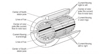
  •  Q4) Explain squirrel cage induction motor?A4)Squirrel cage induction motor consists of the following parts:
  • Stator
  • Rotor
  • Fan
  • Bearings
  • Squirrel Cage Induction Motor Working Principle


     StatorIt consists of a 3- phase winding with a core and metal housing. Windings are such placed that they are electrically and mechanically 120o apart from in space. The winding is mounted on the laminated iron core to provide low reluctance path for generated flux by AC currents. RotorIt is the part of the motor which will be in a rotation to give mechanical output for a given amount of electrical energy. The rated output of the motor is mentioned on the nameplate in horsepower. It consists of a shaft, short-circuited copper/aluminium bars, and a core.The rotor core is laminated to avoid power loss from eddy currents and hysteresis. Conductors are skewed to prevent cogging during starting operation and gives better transformation ratio between stator and rotor.FanA fan is attached to the back side of the rotor to provide heat exchange, and hence it maintains the temperature of the motor under a limit.BearingsBearings are provided as the base for rotor motion, and the bearings keep the smooth rotation of the motor.      Q5) Explain slip ring induction motor?      A5) The slip ring induction motor construction is important. The construction which                includes two parts: Stator and Rotor.
  • Stator
  • Rotor
  •  StatorThe stator of this motor comprises of various slots that are arranged to support the construction of a 3-phase winding circuit connecting to a 3-phase AC source.RotorThe rotor of this motor consists of a cylindrical core with steel laminations. Besides this, the rotor has parallel slots to accommodate 3-phase windings. The windings in these slots are arranged at 120 degrees to each other. This arrangement can reduce noise and avoid irregular pausing of a motor.This motor runs on the principle of Faradays law of electromagnetic induction.  When a stator winding is excited with an AC supply, the stator winding produces magnetic flux. Based on faraday’s law of electromagnetic induction, the rotor winding gets induced and generates a current of magnetic flux. This induced EMF develops torque that enables the rotor to rotate.

      Slip is defined as the difference between the flux speed and the rotor speed. For an induction motor to produce torque, at least some difference should be there between stator field speed and rotor speed. This difference is called ‘slip’. The Slip Ring” is an electromechanical device that aids in transmitting power and electrical signals from stationary to a rotating component.Slip rings are also known as rotary electrical interfaces, electric rotary joints, swivels, or collector rings. Sometimes, based on the application, the slip ring requires higher bandwidth to transmit data. Slip rings improve the efficiency and performance of a motor by improving system operation and eliminating wires that are dangling from motor joints.Slip Ring Induction Motor Resistance CalculationThe peak torque occurs if

    r = Smax. X —— (I)

    Where, Smax = Slip at pull-out torqueX = Inductance of a rotorr = resistance of rotor windingAdding external resistance R to equation (I),

    r+R= (Smax)’. X —— (ii)


    From equation (i) and (ii),

    R = r(S’ max/Smax – 1) —— (iii)

    By definition of Smax, we get Smax = 1 – (Nmax/Ns) —— (iv)

    Putting S’max =1 in equation (iii), we get


    R = r. (1/Smax-1) —— (v)

    Let’s say, Ns = synchronous speed of 1000rpm and pull-out torque happens at 900 rpm, equation (iv) reduces to Smax = 0.1 (i.e., 10% slip)

    Substitute in equation (v),

    R = r. (1/0.1 – 1)

    R = 9. r

    ‘r’ is measured using a multimeter. The resistance value of 9 times higher than of a slip ring rotor resistance is connected externally to experience maximum starting torque.Q6) Explain the torque equation of Induction motor?A6)Torque produced in induction motor depends upon the following factors1.The rotor power factors (CosФ) under running condition2.The rotor current under running condition
  • The part of RMF which induces EMF in rotor wdgi.e. flux (Ф)
  • We can mathematically say that,

    ,    As per DC (M) equation

      But in case of induction motor

    Suffix 1 -> used for stator/stator parts (qty)

    Suffix 2-> used for rotor/rotor parts(qty)


    Therefore,    ----(1)


    = flux that induces the EMF in rotor

    = rotor current under running condition

    = P.F of rotor

    But,stator vtgalso i.e

    ----(2)

    Transformation ratio i.e. given by

    Therefore, 

    and hence


    also

    at slip ’S’ is given by

    And also at slip ‘S’ is =S.

    Hence in equation can be replaced by 

    i.e. U

    =----(3)----()

    4 =------(4)

    Substract (3) and (4) into (1) equation we get,


    (N-m) , Torque equation of I.M.


    At starting condition slip S=1

    So,

      Q7) Explain the applications of Induction motor?A7)
  • The Wound rotor induction motors are also used for loads having high inertia, which results in higher energy losses.
  • Used for the loads which require a gradual build-up of torque.
  • Used for the loads that require speed control.
  • The wound rotor induction motors are used in conveyors, cranes, pumps, elevators and compressors.
  • The maximum torque is above 200 percent of the full load value while the full load slip may be as low as 3 percent. The efficiency is about 90 %.
  •   Q8) Explain the applications of synchronous generator?A8)Synchronous motors are used for applications where precise and constant speed is required. Low power applications of these motors include positioning machines. These are also applied in robot actuators. Ball mills, clocks, record player turntables also make use of synchronous motors. Besides these motors are also used as servomotors and timing machines. 

    9.     A three phase 15hp,460V , 4-pole 60 Hz 1728 rpm induction motor delivers full output power to the load connected to its shaft. The wind age and friction loss of the motor is 750 W. Determine the

  • Mechanical power developed
  • Air gap power
  • Rotor copper loss
  •  

    Full load shaft power = Pout = 15.746

    Mechanical power = Pm = Pout + ∆ Pm = 11190 + 750 = 11940 W

    Air gap power Pavg = Pm / 1-s

    Ns = 120.6/4 = 1800 rpm

    S = ns – n /ns = 1800 – 1728 /1800 =0.04

    Pag = 11940/1-0.04 = 12.437.5 W

    Rotor copper loss ∆Pα = 0.04 x 12.437.5 = 497.5 W

     Q9) A 3-phase, Y connected, round rotor synchronous generator rated at 10kVA, 230V has a Synchronous reactance of 1.2Ω per phase and an armature resistance of 0.5 Ω per phase. Calculate: a) The percentage voltage regulation at full-load with 0.8 lagging power factor. b) The percentage voltage regulation at full-load with 0.8 leading power factor. c) The power factor such that the regulation is zero on full load.  Solution

      Mativa) |Ia  f.l| = S rated/ V rated = 10 x 10 3/ 230/    = 25.4 A

                                 25.1 < -36.87

                        E = Vt + Ia(Ra + jXs) = 230<0/  + (25.1)<-36.8 x (0.5 + 1.2j)

                        = 161.7 < 5.8 V

                               =  |E| - |Vt|/ |Vt|  = 161.7 – 230/3 / 230/ = 21.89 %


    b) Ia = 25.1 < 36.87 A


    E = 230/  + 25.1 <36.8 < 0.5 + 1.2 j= 128.7 < 14.2 V

      articles on Electrical &