PHY
UNIT- 2ELASTIC PROPERTIES OF MATERIALS Q1) A load of 4.0 Kg is suspended from a ceiling through a steel wire of radius 2.0 mm. Find the tensile stress developed in the wire when equilibrium is achieved .Take g=3.1 π m/s2. A1) The Tension of the wire is F= 4.0 X 3.1 π N. The area of cross-section is A= πr2 = π x (2.0 x 10⁻³ m)2 A = 4.0 π x 10-6 m2Thus the tensile stress developed F/A = 4 X 3.1π / 4.0π x 10 N/m2Stress = 3.1 x 10⁶ N/m2 Q2) A copper wire of 3 m length and 1 mm diameter is subjected to a tension of 5N. Calculate the elongation produced in the wire if the young’s modulus of elasticity of copper is 120Gpa. A2) Young’s Modulus Y = FL/Al l = FL/AY = (5 x 3) /π x(0.5 x 10⁻³)2 x 120 x109 = 15.9 x 10⁻³ m Q3) A cylindrical wire of length 1m and radius 5 mm is rigidly clamped at one end. Calculate the couple required to twist the free and through an angle 450. The rigidity modulus of the material of the wire is 200 X 109 Pa A3) Given L = 1 m , r = 5 mm , ‖ = 450 = 45 x π /3600 η =200 X 109 Pa C =  C= 54.056 NmQ4) State Hooke’s law?A4) Hooke's LawIn 17ᵗʰ century physicist RobertHooke observed that the stress vs strain curve for many materials has a linear region. Hooke's law: Within the elastic limits, the strain produced in a body is directly proportional to the stress which causes it. i.e., strain ∝ stress or stress ∝ strain So
  = constant This constant is called 'modulus of elasticity.Hooks law can be defined as The force required to stretch an elastic object such as a metal spring is directly proportional to the extension of the spring. This is known as Hooke's law and commonly written: F=−kx Where F is the force,x is the length of extension/compression k is a constant of proportionality known as the spring constant which is usually given in N/m. Negative sign signify that the restoring force due to the spring is in the opposite direction to the force which caused the displacement. Dimensional Formula [ML-1T-2] The total length L of a spring under extension is equal to the nominal length L0 plus the extension x, L=L0+x and during compression of spring, it is given by L=L0 – x. Q5) Define stress and strain. Write their units. A5) Deformation is the change in shape of the body when a force is applied on it. Even very small magnitude of forces is enough to cause some deformation. Two terms describe the forces on objects undergoing deformation:
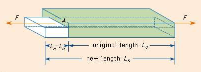
 Stress Strain STRESS When an external force is acting on an elastic body, it causes deformation that means change in shape or in size or both. Stress = Force/Area = F/AThe stress is defined as the restoring force acting on unit area.Unit: The unit for stress is Newton Metre-2 or Nm-2 or Pascal written as Pa.Restoring Force: Due to elastic property, a force is developed within the material, which is equal and opposite to the applied force, this force is responsible to bring the body to its original shape and size. This force is Restoring Force.Since the applied force and the restoring force are equal in magnitude, the ‘stress’ is measured as the applied force acting per unit area.When the applied force tends to compress the body, the stress is compressive stress. When it tends to increase the length in the direction of the force, it is tensile stress. When it acts parallel to the surface of a body, the stress is tangential stress or Shear stress. When an object is being squeezed from all sides, like a submarine in the depths of an ocean, we call this kind of stress a bulk stress or volume stress. STRAINWithin the elastic limits, the strain produced in a body is directly proportional to the stress which causes it. i.e. strain ∝ stress or stress ∝ strain Strain: Change in dimensions to original dimensions is known as Strain. Unit: it has no unit. Q6) Name the types of strains and define it?A6) Types of Strain (1) Linear Strain:When a wire or bar is subjected to two equal and opposite forces namely pulls at its ends there is an increase in the length. If the forces are tensile, the body is elongated. If the forces are compressive, the length is shortened in the direction of the forces. This is called the 'linear strain'.The linear strain is defined as the ratio of change in length to the original length. If the change (increase or decrease) in length is ' 5m ' in a wire or bar of original length L=20m. Linear strain = Change in length/ original length = 5m/20m = 0.25 As the linear strain is ratio of lengths, it has no unit. (2) Bulk (or) Volume Strain: When a force is applied uniformly and normally to the entire surface of the body, there is a change in volume of the body, without any change in its shape. This strain is called 'bulk or volume strain.Volume strain is defined as the ratio of change in volume to the original volume. If 'v' is the change in volume produced in a body of original volume ‘V’Bulk or volume strain = Change in volume v / original volume VIt has also no unit.(3) Shearing (or) Rigidity strain:When a force is applied parallel to one face of a body, the opposite side being fixed, there is a change in shape but not in size of the body. This strain is called the shearing strain. Solids alone can have a shearing strain. It is measured by the angle of the shear 'θ' in radian. Q7) Discuss the three types of elasticity?A7) TYPES OF ELASTICITYCorresponding to the three types of strain, there are three kinds of moduli of elasticity. They are Young’s modulus (Y) Bulk modulus (K) Rigidity modulus (η) Modulus is defined as ratio between stress and strain.1. YOUNG’S MODULUS (Y) The young’s modulus (Y) is defined as ratio of linear or longitudinal stress to linear or longitudinal strain. Y=  =
=  ……..(1)Consider a rod of initial length L0 and cross-sectional area ' A', undergo an extension l, when a stretching force 'F', is applied in the direction of its length. The modulus of elasticity in this case is called Young's modulus and is given by Y =
Whereas linear stress is given by = =
=  ……..(2) Linear strain is given by =
 =
=  ……..(3)By using (2) and (3) in equation (1) we get Y =
  =
=  =
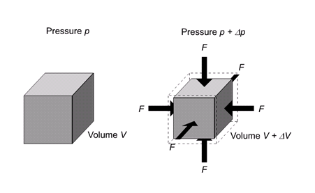
=  where change in length ∆L =Ln-L0 can be written as l.The unit for Young’s modulus is newton metre-2 with symbol N m-2. The single term unit which is widely used for Young's modulus is 'pascal' with symbol 'Pa'. BULK MODULUS (K) When uniform force is applied normally to the surface of the entire body, it produces a change in volume without any change of shape.
It is defined as the ratio of bulk stress to bulk strain. The force applied per unit area or pressure gives the bulk stress. The change in volume per unit volume gives the bulk strain.Bulk stress =  = ΔpΔp – Change in pressureBulk Strain =
  =
=  Bulk Modulus (K) =
  =
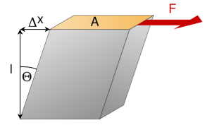
=  The negative sign indicates when the pressure applied increases, the volume decreases.SHEARING (OR) RIGIDITY MODULUS 'Η'The ratio of the shearing stress applied to the body to the shearing strain produced is called the rigidity modulus and denoted by the letter 'η'.
If T is the tangential force/unit area and if θ is the angle of shear measured in radian, Then rigidity modulus η =  =
=  =
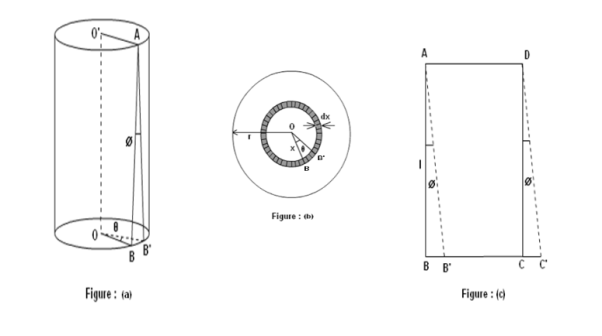
=  The unit for rigidity modulus is newton metre-2 radian-1 with symbol N m-2 rad-1. The other unit which is widely used for rigidity modulus is Pascal radian-1 with symbol Pa rad-1.Q8. Derive a relation for twisting couple on a cylinder or wire-shaft?A8. Consider a cylindrical rod of length l radius r and coefficient of rigidity η. Its upper end is fixed and a couple is applied in a plane perpendicular to its length at lower end as shown in figure.
Consider a cylinder is consisting a large number of co-axial hollow cylinders. Now, consider a one hollow cylinder of radius x and radial thickness dx as shown in fig.(b). Let θ is the twisting angle. The displacement is greatest at the rim and decreases as the center is approached where it becomes zero.As shown in figure (a), Let AB be the line parallel to the axis OO’ before twist produced and on twisted B shifts to B’, then line AB become AB’. Before twisting if hollow cylinder cut along AB and flatted out, it will form the rectangular ABCD as shown in figure (c). But if it will be cut after twisting it takes the shape of a parallelogram AB’C’D.The angle of shear ∠BAB’ = ɸFrom fig.(c) BB’= LɸFrom fig.(b) BB’= xθSo Lɸ= xθAnd ɸ =  The modules of rigidity is η =
  =
=  F = ηɸ =η
 The surface area of this hollow cylinder = 2πxdx
∴ Total shearing force on this area =η 2πxdx=
  x2dxThe moment of this force=
  x2dx. X=
 x3dxNow, integrating between the limits x = 0 and x = r, We have, total twisting couple on the cylinder=
 =
=  =
= [
[ ]∴ Total twisting couple=
 Then, the twisting couple per unit twist (θ= 1) isC =
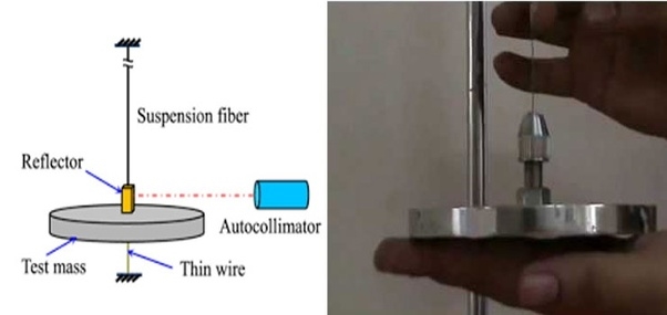
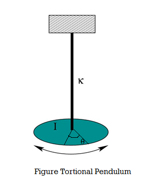
  This twisting couple per unit twist is also called the torsional rigidity of the cylinder or wire.Q9) What is Torsional Pendulum? Find rigidity for it?A9) A heavy cylindrical rod or disc, suspended from the end of a fine wire, whose upper end is fixed is called torsional pendulum.
The rod or disc is turned, the wire will twist and when released, it executes torsional vibrations about the axis. Let θ be the twisting angle. Then the restoring couple set up in it is.
When the disc is rotated in a horizontal plane so as to twist the wire, the various elements of the wire undergo shearing strains and the restoring couple produces the oscillations. If the angle of twist at the lower end of the wire is θ, then the restoring couple is Cθ, where, C - torsional rigidity. This couple acting on the disc produces in it an angular displacement, therefore from the law of conservation of energy, the energy of the system is conserved: Total energy of the Torsional pendulum = Potential Energy + Kinetic Energy -- (1)Then the restoring couple through an angle θ =
= dθPotential Energy (PE) = Cθ2 /2 ---------------- (2)The kinetic energy of the disc (KE) = ½ I ω2 ------------------ (3)Then total energy (TE) = Cθ2 /2 + ½Iω2 = Constant ------------ (4)Differentiating equation (4) with respect to timeCθ
 +Iω
+Iω = 0Since the angular velocity ω =
  and an angular acceleration
  =
=  We can writeCθ
 +I
+I = 0
= 0 (Cθ +I
 ) = 0Where
  ≠ 0Cθ +I
 = 0
= 0  = -
= - θ------------ (5)Angular acceleration = -
 θ------------ (6)( -) Negative sign indicates angular acceleration in opposite direction. Torsional oscillation belongs to simple harmonic motion, Hence the period of oscillationT = 2π
  T = 2π
  T = 2π
  ------------ (7)C - Twisting couple Twisting couple C =
 ------------ (8)Substituting the equation (8) in equation (7)T = 2π
  T = 2π
  ------------ (9)Squaring the equation (9) on both sidesT2 = 4π2
 η =
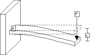
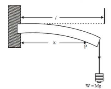
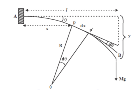
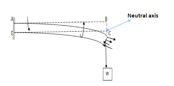
η =  Q10) What is Cantilever? Derive relation for Depression of Cantilever?A10) A beam clamped horizontally at one end and loaded with a weight at the free end is called a cantilever.
Consider a section at P at a distance x from the fixed end. Neglecting the weight of the part between P and the free end, the moment of the external couple = Mg(l - x)The bending moment of the section at P = , where R is the radius of curvature of the neutral axis at P.
Figure: Depression at the free end of cantileverAt equilibrium, Mg(l - x) =  R =
R =  ------------ (1)From this expression we find that as x increases, R also increases, the maximum and minimum values being at the free and fixed ends respectively. Since the radius of curvature of the neutral axis (R) varies from point to point of the cantilever (x), the bending is said to be non-uniform. Let P’ be another point on the bent cantilever at a small distance dx from P. Since P and P’ are very near we can assume that the radius of curvature R is practically the same and O is its centre of curvature. Let the angle between the tangents at P and P’ be dθ.Then angle POP’ = dθdx = RdθR =
  ------------ (2) Substituting the equation (2) in (1)dθ=
  dx ------------ (3) If θ is the angle between the tangents at A and B, we haveθ =
  θ =
θ =  -
-  θ =
θ =  -
-  θ =
θ =  -
-  θ =
θ =  ------------ (4) Deflection of cantilever If dy is the depression of B due to the curvature at PP’dy = (l-x) dθ dθ = (l-x) / dy ------------ (5)Substituting the equ.(5) in (3)dy =
  dxThe depression y is given byy =
  y =
y = y =
y = y =
y = ]y =
]y = Case I For rectangular cross section If b is the breadth and d is the thickness of the beam then Ig becomesIg =
 Substituting the value of Ig in the above (cantilever) equation The depression produced at free end for a rectangular cross sectiony =
 y =
y = Case IIFor circular cross section If r is the radius of the circular cross section, then Ig =
 Substituting the value of Ig in the above (cantilever) equation Depression produced y =
 y =
y = Q11) Write various factors that affect elasticity?A11) It is found that bodies lose their elastic limit, due to elastic fatigue. Therefore, the manufacture should choose the material in such a way that it should regain its elastic property even when it is subjected to large number of cycles of stress. For example substances like quartz, phosphor, bronze etc. May be employed in manufacturing of galvanometers, electrometers etc. after knowing their elastic properties. Apart from elastic fatigue some material will have change in their elastic property because of the following factors.
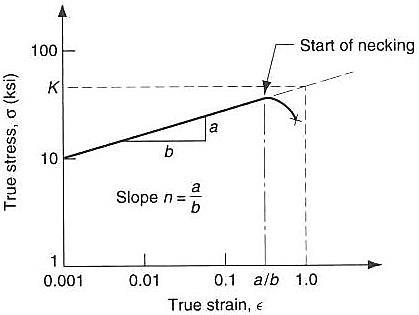
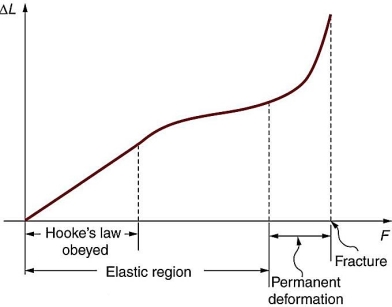
Effect of stress Effect of annealing Hammering and Rolling temperature Effect of impurities Effect of nature of crystals Effect of Stress When a material is subjected to a large number of cycles of stresses, it loses its elastic property even within elastic limit, it results in the formation of large crystal grain, which reduces the elastic property of the material. Taking these into account, the working stress on an engineering piece is kept far below its ultimate tensile strength. Therefore the working stress on the material should be kept lower than the ultimate tensile strengthen and the safety factor. 2. Effect of AnnealingAnnealing is a process by which the material is heated to a very high temperature and then it is slowly cooled. Usually this process is adopted for the material to increase the softness and ductility in the material. But if annealing is made to a material it results in the formation of large crystal grains, which ultimately reduces the elastic property of the material. 3. Hammering and RollingCrystal grains break up into smaller units by Hammering and rolling. This results in increase in elasticity of material. 4. Effect of temperatureIntermolecular forces decrease with increase in temperature so The elastic property of the materials decreases with the rise in temperature. Normally the elasticity increases with the decrease in temperature and vice-versa. Examples1. Lead is not a good elastic material. But at low temperature it becomes a very good elastic material. The elastic property of lead increases when the temperature is decreased.2. A carbon filament which is highly elastic at normal temperature becomes plastic when it is at high temperature3. Invar is a special alloy used for making pendulums and its elasticity is not affected by the temperature change in the normal temperature range.5. Effect of impuritiesThe addition of impurities produces variation in the elastic property of the materials. The increase and decrease of elasticity depends upon the type of impurity added to it.Examples:1. When potassium is added to gold, the elastic property of gold increases.2. When carbon is added to molten iron, the elastic property of iron decreases provided the carbon content should be more than 1% in iron.6. Effect of Nature of crystalsThe elasticity also depends upon the types of the crystals, whether it is a single crystal or poly crystals. For a single crystal the elasticity is more and for a poly crystal the elasticity is less. Q12) Write a note on elasticity?A12) Unlike fluids, solids do not respond to outside force by flowing or easily compressing. The term elasticity refers to the manner in which solids respond to stress, or the application of force over a given unit area. An understanding of elasticity—a concept that helps to illuminate the properties of objects from steel bars to rubber bands to human bones.Elasticity, ability of a deformed material body to return to its original shape and size when the forces causing the deformation are removed. A body with this ability is said to behave (or respond) elastically.Most solid materials exhibit elastic behaviour to a greater or lesser extent, but there is a limit to the magnitude of the force and the accompanying deformation within which elastic recovery is possible for any given material. This limit, called the elastic limit.Elastic limit is the maximum stress or force per unit area within a solid material that can arise before the onset of permanent deformation. Stresses beyond the elastic limit cause a material to yield or flow. For these type of materials the elastic limit tells the end of elastic behaviour and the beginning of plastic behaviour. But for some brittle materials, stresses beyond the elastic limit result in fracture. No plastic deformation exists in these types of cases.Metals and ElasticityMetals, in fact, exhibit a number of interesting characteristics with regard to elasticity. With the notable exception of cast iron, metals tend to possess a high degree of ductility, or the ability to be deformed beyond their elastic limits without experiencing rupture. Up to a certain point, the ratio of tension to elongation for metals is high: in other words, a high amount of tension produces only a small amount of elongation. Beyond the elastic limit, however, the ratio is much lower: that is, a relatively small amount of tension produces a high degree of elongation.For example, a steel bar or wire can be extended elastically only about 1 percent of its original length, while for strips of certain rubber like materials, elastic extensions of up to 1,000 percent can be achieved. Thus elastic limit depends on the type of solid considered.Steel is much stronger than rubber, however, because the tensile force required to effect the maximum elastic extension in rubber is less (by a factor of about 0.01) than that required for steel. The elastic properties of many solids in tension lie between these two extremes.The different macroscopic elastic properties of steel and rubber are because of the different microscopic structures. Here is the point to note that the elasticity of steel and other metals arises from short-range interatomic forces that, when the material is unstressed, maintain the atoms in regular patterns. Under stress the atomic bonding can be broken at quite small deformations. Whereas at the microscopic level, rubber like materials and other polymers consist of long-chain molecules that uncoil as the material is extended and recoil in elastic recovery. The mathematical theory of elasticity and its application to engineering mechanics is concerned with the macroscopic response of the material and not with the underlying mechanism that causes it.The elastic limit is in principle different from the proportional limit, which marks the end of the kind of elastic behaviour that can be described by Hooke’s law, namely, that in which the stress is proportional to the strain (relative deformation) or equivalently that in which the load is proportional to the displacement. The elastic limit nearly coincides with the proportional limit for some elastic materials, so that at times the two are not distinguished; whereas for other materials a region of non-proportional elasticity exists between the two.Gases and liquids also possess elastic properties since their volume changes under the action of pressure. For small volume changes, the bulk modulus, κ, of a gas, liquid, or solid is defined by the equation P = −κ(V−V0)/V0, where P is the pressure that reduces the volume V0 of a fixed mass of material to V. Since gases can in general be compressed more easily than liquids or solids, the value of κ for a gas is very much less than that for a liquid or solid. By contrast with solids, fluids cannot support shearing stresses and have zero Young’s modulus. BonesThe tensile strength in bone fibers comes from the protein collagen, while the compressive strength is largely due to the presence of inorganic (non-living) salt crystals. It may be hard to believe, but bone actually has an ultimate strength, both in tension and compression,greater than that of concrete.The ultimate strength of most materials is rendered in factors of 108 N/m2—that is, 100,000,000 newtons (the metric unit of force) per square meter. For concrete under tensile stress, the ultimate strength is 0.02, whereas for bone, it is 1.3. Under compressive stress, the values are 0.2 and 1.7, respectively. In fact, the ultimate tensile strength of bone is close to that of cast iron (1.7), though the ultimate compressive strength of cast iron (5.5) is much higher than for bone.It may be hard to understand how bone can be stronger than concrete, but that is largely because the volume of concrete used in most situations is much greater than the volume of any bone in the body of a human being. By way of explanation, consider a piece of concrete no bigger than a typical bone: under relatively small amounts of stress, it would crumble.Q13) Write a note on plasticity? A13) The property of the material by virtue of which it does not regain its original shape when the external force acting on it is removed. It is called plasticity. Plasticity.It is also known as plastic deformation, is the ability of a solid material to undergo permanent deformation.Under the effect applied forces a non-reversible change of shape is occur. The transition from elastic behaviour to plastic behaviour is known as yielding.Paraffin wax, wet clay are the nearest approach to a perfectly plastic bodies.The solid acquires a permanent change in its structure if, on restoring the external environment (under which the deformation process has taken place) to the initial configuration, the solid fails to restore to the initial structure. The quantifiers for such structural changes can be the shape of the body (at a macroscopic level of observation) or a rearrangement of defects (at a microscopic level of observation).Unlike elasticity, plasticity is fundamentally a microscopic phenomenon.To illustrate the phenomenon of plasticity we consider a simple example of stretching a metal wire (with cylindrical cross-section) under an isothermal environment. A representative element of the wire is selected and the following two quantities are measured: The force per unit cross-sectional area (stress) and The change in length of the element with respect to some fixed reference state (strain). Below a certain critical value of stress and strain, the element under observation returns to its original state of stress and strain upon removal of the external mechanism for stretching. The collection of all such stress/strain values forms the elastic range associated with the material. The deformation remains elastic as long as the stress/strain values are restricted to the elastic range. For values beyond the elastic range, the element will undergo permanent structural changes. The boundary of the elastic range signifies the onset of plastic deformation and therefore can be appropriately termed as the yield limit for the transition from an elastic to a plastic deformation process. It should however be noted that for most materials an accurate measurement of the yield limit is difficult because of the gradual nature of the transition from elastic to plastic behaviour. It then becomes a matter of convention to choose an appropriate yield limit for such materials. Based on the nature of the yield limit, we distinguish between two models of plastic flow. The first model is known as perfect plasticity (or the ideal plastic flow), wherein the yield limit for stress is assumed to remain constant. The second model, however, allows the yield stress to vary with the structural changes in the body Note from that for a zero strain, the stress does not necessarily vanish. This can be attributed to the presence of microstructure in the form of defects in the unstrained state, which induces internal stresses so as to maintain an equilibrium configuration of defects in the element. Plasticity, ability of certain solids to flow or to change shape permanently when subjected to stresses of intermediate magnitude between those producing temporary deformation, or elastic behaviour, and those causing failure of the material, or rupture (see yield point). Plasticity enables a solid under the action of external forces to undergo permanent deformation without rupture. Elasticity, in comparison, enables a solid to return to its original shape after the load is removed. Plastic deformation occurs in many metal-forming processes (rolling, pressing, forging) and in geologic processes (rock folding and rock flow within the earth under extremely high pressures and at elevated temperatures).Plastic deformation is a property of ductile and malleable solids. Brittle materials, such as cast iron, cannot be plastically deformed, though at elevated temperatures some, such as glass, which is not a crystallized solid, do undergo plastic flow.Q14) Write a note on strain hardening and strain softening?A14) Strain hardening (also called work-hardening or cold-working) is the process of making a metal harder and stronger through plastic deformation.In the plastic region, the true stress increases continuously i.e when a metal is strained beyond the yield point, more and more stress is required to produce additional plastic deformation and the metal seems to have become more stronger and more difficult to deform. This implies that the metal is becoming stronger as the strain increases. Hence, it is called "Strain Hardening". The plastic portion of the true stress-strain curve (or flow stress curve) plotted on a log-log scale gives the n value as the slope and the K value as the value of true stress at true strain of one.
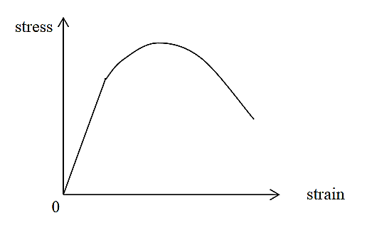
Figure 21log(ø) = log(K)+ n x log(e)For materials following the power law, the true strain at the Ultimate Tensile Strength is equal to n. when you plot the log-log plot, use data points after the yield point (to avoid elastic points) and before instability (necking).A material that does not show any strain hardening (n=0) is classed as perfectly plastic. Such a material would show a constant flow stress irrespective of strain. K can be found by substituting n and a data point (from the plastic region) in the power law or from the y-intercept.Strain hardening reduces ductility and increases brittleness. e.g.Cold-working can be easily demonstrated with piece of wire or a paper clip. Bend a straight section back and forth several times. Notice that it is more difficult to bend the metal at the same place. In the strain hardened area dislocations have formed and become tangled, increasing the strength of the material. Continued bending will eventually cause the wire to break at the bend due to fatigue cracking.Stain Softening Strain softening is defined as the region in which the stress in the material is decreasing with an increase in strain. This can be observed in certain materials after yielding point. It causes deterioration of material strength with increasing strain, which is a phenomenon typically observed in damaged quasi brittle materials, including fibre reinforced composites and concrete. It is primarily a consequence of brittleness and heterogeneity of the material.Strain Softening Materials can also strain soften, for example soils. In this case, the stress-strain curve “turns down” as shown in figure. The yield surface for such a material will in general decrease in size with further straining.
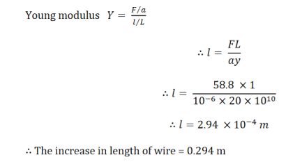
Figure 2: uniaxial stress-strain curve for a strain-softening material Q15) The modulus of rigidity and Poisson’s ratio of the material of a wire are 2.87 x 10¹⁰ N/m2 and 0.379 respectively. Find the value of Young’s modulus of the material of the wire. A15) Here, η = 2.87 x 10¹⁰ N/m2 and σ = 0.379 We know that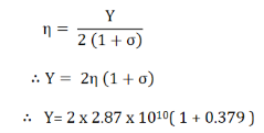 Y = 7.915 x 10¹⁰ N/m2 Q16) A steel wire, 1 meter long and 1 mm square in cross section, supports a mass of 6 kg. By how much does it stretch? (Give Y = 20 x 1010 N/m-2) A16) Here, L = 1 mA = 1 sq. mm = 10-6 sq. m m = 6 kg. l = ? The stretching force F = mg = 6 x 9.8 = 58.8 N
Q17) Write a note on fracture?A17) Fracture is the separation of an object or material into two or more pieces under the action of stress. The fracture of a solid usually occurs due to the development of certain displacement discontinuity surfaces within the solid. If a displacement develops perpendicular to the surface of displacement, it is called a normal tensile crack or simply a crack; if a displacement develops tangentially to the surface of displacement, it is called a shear crack. Brittle fractures occur with no apparent deformation before fracture; ductile fractures occur when visible deformation does occur before separation.Fracture strength, also known as breaking strength, is the stress at which a specimen fails via fracture. This is usually determined for a given specimen by a tensile test, which charts the stress-strain curve. The final recorded point is the fracture strength.Bones, on the whole, do not fracture due to tension or compression. Rather they generally fracture due to sideways impact or bending, resulting in the bone shearing or snapping. The behaviour of bones under tension and compression is important because it determines the load the bones can carry.
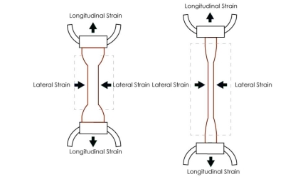
Figure 3: FractureBones are classified as weight-bearing structures such as columns in buildings and trees. Weight-bearing structures have special features; columns in building have steel-reinforcing rods while trees and bones are fibrous. The bones in different parts of the body serve different structural functions and are prone to different stresses. Thus, the bone in the top of the femur is arranged in thin sheets separated by marrow while, in other places, the bones can be cylindrical and filled with marrow or just solid. Overweight people have a tendency toward bone damage due to sustained compressions in bone joints and tendons.Q18) What do you mean by Poisson’s Ratio?A18) POISSON RATIO (σ)Poisson’s Ratio consists of strain and stress that we use in the direction of the stretching force. Furthermore, It relates to the tensile strength of an object.Extension and contraction are opposite types of linear strain. Extension means to get longer. Contraction means to get shorter. Whenever a material is extended or contracted by a linear stress in one direction (called the x axis), the reverse strain usually takes place in the perpendicular directions (the y and z axes). The direction of a linear stress is called the axial direction. All the directions that are perpendicular to this are called the transverse directions.An axial extension is usually accompanied by a transverse contraction. Stretching a piece of dough makes it get thinner as well as longer. An axial contraction is usually accompanied by a transverse extension. Flattening a piece of dough makes it get wider and longer as well as thinner. We also refer it to as Poisson Ratio, Poisson coefficient or coefficient de Poisson. In addition, it is usually represented by σ.
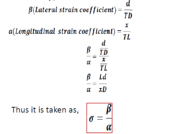
Figure 7:Poisson’s RatioWithin the elastic limit, the lateral strain (β) is proportional to the linear or longitudinal strain (α) and the ratio between them is a constant, called Poisson’s ratio (σ)
There are no units for Poisson’s ratio. It is a pure number and hence a dimensionless quantity.Let us consider the ratio β/αThus it is taken as,
If the body under tension suffers no lateral strain then Poisson’s ratio is zero. Q19) Derive a relation between young’s modulus (Y), bulk modulus (K) and rigidity modulus (η) ?A19) EXPRESSION FOR YOUNG'S MODULUS (Y), BULK MODULUS (K) AND RIGIDITY MODULUS (η) IN TERMS OF  Bulk Modulus - Deformation of cube Let us consider a unit cube ABCDEFGHA. Suppose force Tx, Ty and Tz are acting perpendicular to the faces BEHD and AFGC, ABDC and EFGH, ABEF and DHGC respectively, as shown in figure. Let ‘α’ be the increase per unit length per unit tension along the direction of the force and ‘β’ be the contraction produced per unit length per unit tension direction perpendicular to the force. Due to the applied force,The elongations produce in the edges AB = TxαThe elongations produce in the edge BE = TyαThe elongations produce in the edge BD = TzαSimilarly, The contraction produced in the perpendicular to the edge AB = TxβThe contraction produced in the perpendicular to the edge BE = TyβThe contraction produced in the perpendicular to the edge BD = Tzβ
Figure 8:Deformation of cube –Bulk ModulusThe length of edges after elongation and contraction becomes, The volume of cube becomes
Neglecting squares and products of α and β. In the case of bulk modulus, the force acting uniformly in all the directions, Hence, The original volume of cube is unity; therefore increase in volume of the cube
  If pressure P is applied instead of tension T out words, the cube compressed and the volume decreased by the amount 3P(
 ).Volume strain =
  =
=  Bulk Modulus K =
  =
=  K =
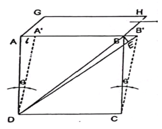
K =  Modulus of rigidity:Consider a cube. Length of the edge of cube is ‘L’. Let shearing force
  be applied on the tope face ABHG of a cube, which produce shear by an angle θand linear displacement ‘l’. The face ABCD changes its position to A’B’CD.Tensile stress =
  =
=  = TShear Strain =
 Modulus of rigidity
  =
=  =
= 
Figure 9:Modulus of rigidityA shearing stress along AB is equivalent to a tensile stress along DB and an equal compression stress along CA at right angles. If αand β are the longitudinal and lateral strains per unit stress respectively. Then extension along diagonal DB due to tensile stress = DB T and, extension along diagonal DB due to compression stress along AC = DB T .Therefore, the total extension along DB = DB T(
 )But, from above figure diagonal DB =
 DB=
DB=  L
L
Young’s ModulusLet us consider unit tension applied on the edge of the unit cube, which produces the extension  linear stress =1 and linear strain =
  =α. RELATION BETWEEN Y,
  AND K, We know that
Subtracting (1) and (2)
Multiplying equation (2) by 2 and adding equations (1) and (2) we get,
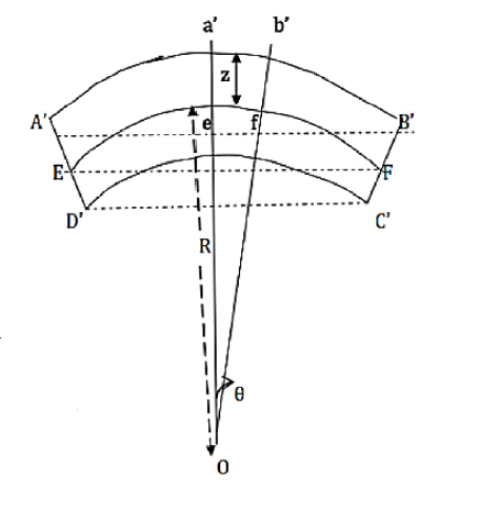
Q20) Derive a relation for bending moment of a beam with circular and rectangular cross?A20) A beam is a structural member whose length is very large compared to other dimensions.The neutral plane or neutral surface is a conceptual plane within a beam or cantilever. When a beam is loaded by putting some wait, force is acting on the beam. Due to this bending force, the beam bends in such a way that the inner surface is in compression and the outer surface is in tension. There exists a neutral plane. Neutral plane is the surface within the beam between these zones, where the material of the beam is not under stress, either compression or tension. As no lengthwise stress force is acting on the neutral plane, there is no strain or extension either: when the beam bends, the length of the neutral plane remains constant. Any line within the neutral plane parallel to the axis of the beam is called the deflection curve of the beam. To show that every beam must have a neutral plane, it is considered that the material of the beam divided into narrow fibers parallel to its length. When the beam is bent, at any given cross-section the region of fibers near the concave side will be under compression, while the region near the convex side will be under tension. Because the stress in the material must be continuous across any cross section, there must be a boundary between the regions of compression and tension at which the fibers have no stress. This is the neutral plane.Consider a beam, now fixed its one end and put some load at the other end. Load will exert force on the beam. Due to this applied force, a force of reaction is set up at the fixed end of the beam. These two equal and opposite forces constitute a couple which tends to rotate the beam. Since the beam is elastic a restoring couple is set up to bring the beam back to equilibrium.The moment of the restoring couple is called bending moment of a beam.
Figure 10: Bending of beamExpression for the bending moment of a beam
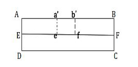
Figure 11: Section of the beam Let us consider a section of beam ABCD. The central line EF is known as the neutral axis. When the beam is under the action of the external couple, the section ABCD of the beam will bend into an arc without any change in length of neutral axis i.e. EF. The upper part of the beam will undergo extension and the portion A’B’ is greater than > AB i.e. A’B’ > AB.The lower part of the beam will be subjected to compressive stresses and the portion C’D’ is less than CD i.e. C’D’ < CD.When the load is put on the beam, the beam is bent into an arc of a circle of radius ‘R’ with the center at O.Consider a small portion of the neutral axis, ef, which is subtending an angle θ at the center of the circle of radius R.Consider another small part a’b’ from the segment AB of the beam and this portion a’b’ is at a distance z, from the neutral axis.
Figure 12: Bending of the beamIn the absence of bending,ef = R θand a’b’ = (R+z)θStrain in the filament=  =
=  =
=  =
= If a is the area of the filament a’b’, which is at a distance z from the neutral axis and Y is the Young’s modulus,
Moment of this force about the neutral axis = F * its distance from neutral axis The bending moment of the beam is obtained by summing over the moments of all
The filaments above and below the neutral axisExpression for bending moment:Bending moment is dependent on momentum of Inertia so based on the momentum of inertia and momentum of inertia is depends on shape.Bending moment for a beam of rectangular cross-section  Where, b and d are the breadth and thickness of the beam respectively. ii. Bending moment for a beam of circular Cross-section
 Where
Where  is the radius of the beam.
 C= 54.056 NmQ4) State Hooke’s law?A4) Hooke's LawIn 17ᵗʰ century physicist RobertHooke observed that the stress vs strain curve for many materials has a linear region. Hooke's law: Within the elastic limits, the strain produced in a body is directly proportional to the stress which causes it. i.e., strain ∝ stress or stress ∝ strain So
  = constant This constant is called 'modulus of elasticity.Hooks law can be defined as The force required to stretch an elastic object such as a metal spring is directly proportional to the extension of the spring. This is known as Hooke's law and commonly written: F=−kx Where F is the force,x is the length of extension/compression k is a constant of proportionality known as the spring constant which is usually given in N/m. Negative sign signify that the restoring force due to the spring is in the opposite direction to the force which caused the displacement. Dimensional Formula [ML-1T-2] The total length L of a spring under extension is equal to the nominal length L0 plus the extension x, L=L0+x and during compression of spring, it is given by L=L0 – x. Q5) Define stress and strain. Write their units. A5) Deformation is the change in shape of the body when a force is applied on it. Even very small magnitude of forces is enough to cause some deformation. Two terms describe the forces on objects undergoing deformation:
  =
=  ……..(1)Consider a rod of initial length L0 and cross-sectional area ' A', undergo an extension l, when a stretching force 'F', is applied in the direction of its length. The modulus of elasticity in this case is called Young's modulus and is given by Y =
|
 =
=  ……..(2) Linear strain is given by =
 =
=  ……..(3)By using (2) and (3) in equation (1) we get Y =
  =
=  =
=  where change in length ∆L =Ln-L0 can be written as l.The unit for Young’s modulus is newton metre-2 with symbol N m-2. The single term unit which is widely used for Young's modulus is 'pascal' with symbol 'Pa'. BULK MODULUS (K) When uniform force is applied normally to the surface of the entire body, it produces a change in volume without any change of shape.
|
 = ΔpΔp – Change in pressureBulk Strain =
  =
=  Bulk Modulus (K) =
  =
=  The negative sign indicates when the pressure applied increases, the volume decreases.SHEARING (OR) RIGIDITY MODULUS 'Η'The ratio of the shearing stress applied to the body to the shearing strain produced is called the rigidity modulus and denoted by the letter 'η'.
|
 =
=  =
=  The unit for rigidity modulus is newton metre-2 radian-1 with symbol N m-2 rad-1. The other unit which is widely used for rigidity modulus is Pascal radian-1 with symbol Pa rad-1.Q8. Derive a relation for twisting couple on a cylinder or wire-shaft?A8. Consider a cylindrical rod of length l radius r and coefficient of rigidity η. Its upper end is fixed and a couple is applied in a plane perpendicular to its length at lower end as shown in figure.
|
 The modules of rigidity is η =
  =
=  F = ηɸ =η
 The surface area of this hollow cylinder = 2πxdx
|
 2πxdx=
  x2dxThe moment of this force=
  x2dx. X=
 x3dxNow, integrating between the limits x = 0 and x = r, We have, total twisting couple on the cylinder=
 =
=  =
= [
[ ]∴ Total twisting couple=
 Then, the twisting couple per unit twist (θ= 1) isC =
  This twisting couple per unit twist is also called the torsional rigidity of the cylinder or wire.Q9) What is Torsional Pendulum? Find rigidity for it?A9) A heavy cylindrical rod or disc, suspended from the end of a fine wire, whose upper end is fixed is called torsional pendulum.
|
|
 =
= dθPotential Energy (PE) = Cθ2 /2 ---------------- (2)The kinetic energy of the disc (KE) = ½ I ω2 ------------------ (3)Then total energy (TE) = Cθ2 /2 + ½Iω2 = Constant ------------ (4)Differentiating equation (4) with respect to timeCθ
 +Iω
+Iω = 0Since the angular velocity ω =
  and an angular acceleration
  =
=  We can writeCθ
 +I
+I = 0
= 0 (Cθ +I
 ) = 0Where
  ≠ 0Cθ +I
 = 0
= 0  = -
= - θ------------ (5)Angular acceleration = -
 θ------------ (6)( -) Negative sign indicates angular acceleration in opposite direction. Torsional oscillation belongs to simple harmonic motion, Hence the period of oscillationT = 2π
  T = 2π
  T = 2π
  ------------ (7)C - Twisting couple Twisting couple C =
 ------------ (8)Substituting the equation (8) in equation (7)T = 2π
  T = 2π
  ------------ (9)Squaring the equation (9) on both sidesT2 = 4π2
 η =
η =  Q10) What is Cantilever? Derive relation for Depression of Cantilever?A10) A beam clamped horizontally at one end and loaded with a weight at the free end is called a cantilever.
|
|
 , where R is the radius of curvature of the neutral axis at P.
|
 R =
R =  ------------ (1)From this expression we find that as x increases, R also increases, the maximum and minimum values being at the free and fixed ends respectively. Since the radius of curvature of the neutral axis (R) varies from point to point of the cantilever (x), the bending is said to be non-uniform. Let P’ be another point on the bent cantilever at a small distance dx from P. Since P and P’ are very near we can assume that the radius of curvature R is practically the same and O is its centre of curvature. Let the angle between the tangents at P and P’ be dθ.Then angle POP’ = dθdx = RdθR =
  ------------ (2) Substituting the equation (2) in (1)dθ=
  dx ------------ (3) If θ is the angle between the tangents at A and B, we haveθ =
  θ =
θ =  -
-  θ =
θ =  -
-  θ =
θ =  -
-  θ =
θ =  ------------ (4) Deflection of cantilever If dy is the depression of B due to the curvature at PP’dy = (l-x) dθ dθ = (l-x) / dy ------------ (5)Substituting the equ.(5) in (3)dy =
  dxThe depression y is given byy =
  y =
y = y =
y = y =
y = ]y =
]y = Case I For rectangular cross section If b is the breadth and d is the thickness of the beam then Ig becomesIg =
 Substituting the value of Ig in the above (cantilever) equation The depression produced at free end for a rectangular cross sectiony =
 y =
y = Case IIFor circular cross section If r is the radius of the circular cross section, then Ig =
 Substituting the value of Ig in the above (cantilever) equation Depression produced y =
 y =
y = Q11) Write various factors that affect elasticity?A11) It is found that bodies lose their elastic limit, due to elastic fatigue. Therefore, the manufacture should choose the material in such a way that it should regain its elastic property even when it is subjected to large number of cycles of stress. For example substances like quartz, phosphor, bronze etc. May be employed in manufacturing of galvanometers, electrometers etc. after knowing their elastic properties. Apart from elastic fatigue some material will have change in their elastic property because of the following factors.
|
|
 Y = 7.915 x 10¹⁰ N/m2 Q16) A steel wire, 1 meter long and 1 mm square in cross section, supports a mass of 6 kg. By how much does it stretch? (Give Y = 20 x 1010 N/m-2) A16) Here, L = 1 mA = 1 sq. mm = 10-6 sq. m m = 6 kg. l = ? The stretching force F = mg = 6 x 9.8 = 58.8 N
|
|
|
|
|
 Bulk Modulus - Deformation of cube Let us consider a unit cube ABCDEFGHA. Suppose force Tx, Ty and Tz are acting perpendicular to the faces BEHD and AFGC, ABDC and EFGH, ABEF and DHGC respectively, as shown in figure. Let ‘α’ be the increase per unit length per unit tension along the direction of the force and ‘β’ be the contraction produced per unit length per unit tension direction perpendicular to the force. Due to the applied force,The elongations produce in the edges AB = TxαThe elongations produce in the edge BE = TyαThe elongations produce in the edge BD = TzαSimilarly, The contraction produced in the perpendicular to the edge AB = TxβThe contraction produced in the perpendicular to the edge BE = TyβThe contraction produced in the perpendicular to the edge BD = Tzβ
|
 The volume of cube becomes
|
 The original volume of cube is unity; therefore increase in volume of the cube
  If pressure P is applied instead of tension T out words, the cube compressed and the volume decreased by the amount 3P(
 ).Volume strain =
  =
=  Bulk Modulus K =
  =
=  K =
K =  Modulus of rigidity:Consider a cube. Length of the edge of cube is ‘L’. Let shearing force
  be applied on the tope face ABHG of a cube, which produce shear by an angle θand linear displacement ‘l’. The face ABCD changes its position to A’B’CD.Tensile stress =
  =
=  = TShear Strain =
 Modulus of rigidity
  =
=  =
= 
|
 .Therefore, the total extension along DB = DB T(
 )But, from above figure diagonal DB =
 DB=
DB=  L
L Therefore, the total extension of diagonal EB’ = In BB’E, Cos BB’E =
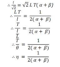
Now, comparing equation (1) and (2), we get
|
 linear stress =1 and linear strain =
  =α. RELATION BETWEEN Y,
  AND K, We know that
|
|
Form equation of young’s modulus,
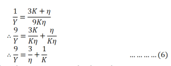
Using equation (5) in (4)
The above equation gives the relation connecting the three elastic constants Y, K and |
|
|
|
 =
=  =
=  =
= If a is the area of the filament a’b’, which is at a distance z from the neutral axis and Y is the Young’s modulus,
|
 The bending moment of the beam is obtained by summing over the moments of all
|
 Where, b and d are the breadth and thickness of the beam respectively. ii. Bending moment for a beam of circular Cross-section
 Where
Where  is the radius of the beam.
 0 matching results found
