PHY
UNIT 3MAXWELL'S EQUATIONS, EM WAVES AND OPTICAL FIBERS Q1)Prove why electromagnetic waves are transverse in nature?OrProve the absence of longitudinal component in em wave?A1) In an electromagnetic wave, electric and magnetic field vectors are perpendicular to each other and at the same time are perpendicular to the direction of propagation of the wave. This nature of electromagnetic wave is known as Transverse nature.Maxwell proved that both the electric and magnetic fields are perpendicular to each other in the direction of wave propagation. He considered an electromagnetic wave propagating along positive x-axis. When a rectangular parallelepiped was placed parallel to the three co-ordinate axis, the electric and magnetic fields propagate sinusoidal with the x-axis and are independent of y and z-axis.A wave in which the values of variable are constant in a plane perpendicular to the direction of propagation of the wave is called plane wave. These planes may also termed as wave fronts.In this section we will study the variation of field of  and
and  of an em plane wave with space and time.Variation With SpaceFirst we will consider the variation with space. Suppose a plane em wave is propagating along x axis. Then the values of the field vectors
  and
and  will be constant on any plane parallel to YZ plane. That is: For
 =
= =
= =
= = 0 …………(1)For
 =
= =
= =
= = 0 …………(2)From Maxwell’s equation for free space, we have∇.E=0 Therefore
  +
+ +
+ =0Which gives
 =0 …………(3) Also From Maxwell’s equation for free space, we have ∇.B=0 we have ∇.H=0 as B = μH Hence
 +
+ +
+ =0Which gives
 =0 …………(4)The equation (3) and (4) show that there is no variation of
  and
and  along the X axis. In other words, there is no variation in the longitudinal component of
  and
and  .Time Variation of
  and
and  The Maxwell’s equation in free space can be written as:∇ x E= -dB/dt or ∇ x E= -μ
 because B = μH Comparing the rectangular components, we find:
 -
-  = -μ
= -μ …………(5)
 -
-  = -μ
= -μ …………(6)
 -
-  = -μ
= -μ …………(7)Applying the condition listed in equation (1), from equation (5), we find:
 -
-  =0
=0 =0 …………(8)Again using Maxwell’s equation for free space is:∇ x H=
  = Ɛ
= Ɛ Comparing the rectangular components, we can write:
 -
-  = Ɛ
= Ɛ …………(9)
 -
-  = Ɛ
= Ɛ …………(10)
 -
-  = Ɛ
= Ɛ …………(11)Again using the conditions listed in equation (2) gives:
 -
-  = 0
= 0 = 0 …………(12)From equation (8) and (12), we find that there is no variation in the values of
  and
and  with time. That is
  and
and  neither vary with space nor with time. So at the most they can have constant value. But the constant values of
  and
and  contribute nothing towards the wave because for the wave the field vectors must possess oscillatory nature. This shows that there is no longitudinal component of the field vectors in the electromagnetic wave. In other words, for the purpose of discussing of the wave nature, we may put
  =0Now from equation 6 and 7 by putting
  = 0, we find:
 = μ
= μ …………(13)
 = - μ
= - μ …………(14)Similarly putting
  =0 in equation (10) and (11) we find:
 = - Ɛ
= - Ɛ …………(10)
 = Ɛ
= Ɛ …………(11)These relations show that in the em values
  and
and  are related to each other. Also
  and
and  are related to each other, and their time or space variation are not zero. From this we conclude that the em wave is transverse in nature. Q2) Derive electromagnetic wave equation?A2) Wave is nothing but a pattern of disturbance which propagates and carry energy with it. You can produce a wave on a rope by moving one end of the rope up and down. The wave produces on rope needs a medium to propagate and here medium is rope itself. This type of waves is known as mechanical waves. But in the case of Electromagnetic waves, they don't need a medium to propagate. Electromagnetic waves are waves that are created as a result of variations of electric field and a magnetic field. Or we can say that Electromagnetic waves are nothing but changing magnetic and electric fields. Electromagnetic waves are also known to be solutions of Maxwell's equations. And Maxwell's equations are the fundamental equations of electrodynamics. Electromagnetic waves can transmit energy and travel through a vacuum. Light waves are examples of electromagnetic waves. Generally, Electromagnetic waves are shown by a sinusoidal graph.
Figure 1As shown in figure Electromagnetic waves consist of time-varying electric and magnetic fields and they are perpendicular to each other and these both fields are also perpendicular to the direction of propagation of waves. Maxwell’s four equations are given by∇·E = ρ/ε0 (1)∇×E = −∂B/∂t (2)∇×H = J + ∂D/∂t (3)∇·B = 0 (4)These equations illustrate the unique coexistence in nature of the electric field and the magnetic field. The first two equations give the value of the given flux through a closed surface, and the second two equations give the value of a line integral around a loop. In this notation,∇=(∂/∂x, ∂/∂y, ∂/∂z)E is the electric vectorB is the magnetic inductionρ is the electric charge density j is the electric current densityε0 is the permittivity of free spacec is the speed of light.In addition to Maxwell equations, the following identities are useful:J = σE (5)D = εE (6)B = μH (7)Here,D is the electric displacement H is the magnetic vectorσ is the specific conductivityε is the dielectric constant (or permittivity) μ is the magnetic permeabilityFree space or non-conducting medium. We know that non conducting medium means no current so conductivity is zero i.e. σ=0 So current density J=σE will also become zero as σ=0 Also free space means no charges which leads to ρ=0. These points mentioned below. (a) No condition current i.e σ=0, thus J=0 ( J=σE)(b) No charges (i.e ρ=0)For the case of no charges or currents, that is, j = 0 and ρ = 0, and a homogeneous medium. Using these the Maxwell equation can rewritten as∇.D=0 or ∇.E=0 as ρ=0 (12)∇ x E= -dB/dt or ∇ x E= -μ dH/dt because B = μH (13)∇ x H=d D/dt or ∇ x H = ε dE/dt (J=0) and D = εE (14)∇.B=0 (15)WAVE EQUATION IN TERMS OF ELECTRIC FIELD INTENSITY, ENow taking curl of second Maxwell’s equation (13) ,we get∇x(∇ x E)=- μ d/dt (∇ x H)Applying standard vector identity, that is [∇ *(∇*E)=∇(∇.E)-∇2E] on left hand side of above equation, we get∇ (∇ .E)-∇2E= -μ d/dt (∇x H) (16)Substituting equations (13) and (14) in equations (16) ,we get-∇2E= – με d/dt (dE/dt)Or ∇2E=με d 2 E/dT2 (17)Equation (17) is the required wave equation in terms of electric field intensity, E for free space . This is the law that E must obey.WAVE EQUATION IN TERMS OF MAGNETIC FIELD INTENSITY, HTake curl of fourth Maxwell’s equation (14) ,we get∇x(∇xH)=ε d/dt(∇xE)Applying standard vector identity that is[∇*(∇*H)=∇ (∇.H)-∇2H]On left side of above equation , we get∇(∇.H)-∇2H= ε d/dt(∇xE) (18)Substituting equations (14) and (13) in equation(18) ,we get-∇2H= – μεd/dt(dH/dt)Or ∇2H=με d2H/dt2 (19)Equations (19) is the required wave equation in terms of magnetic field intensity, H and this is the law that H must obeyFor vacuum μ=μ0 and ε=ε0, equations (17) and (19) will become∇2 E=μ0ε0 d2E/dt2 (20)And ∇2H= μ0ε0 d2H/dt2 (21)This leads to an expression for the velocity of propagationFrom equation both equations (20) and (21) have the form of the general wave equation for a wave  (x,t) traveling in the x direction with speed v. Equating the speed with the coefficients, we derive the speed of electric and magnetic waves, which is a constant that we symbolize with “c”It is useful to note that in vacuumc2=1/ε0μ0 Where μ0 is the permeability of free space
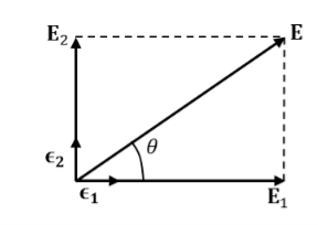
 Let us rewrite the equation (20) and (21) for one dimension.Or d 2 E/dx2 = μ0ε0 d 2 E/dt2 (22)d2H/dx2 = μ0ε0 d2H/dt2 (23)The simplest solutions to the differential equations (22) and (23) are sinusoidal wave functions:E(x) = Emax cos(kx-t) (24)B(x) = Bmax cos(kx-t) (25)where k = 2π/λ is the wavenumber ,ω = 2πƒ is the angular frequency, λ is the wavelength, f is the frequency and ω /k=f=v= c. Q3) Discuss the polarization of em wave? A3) There is more to be said about the complex vector amplitudes Ɛ and B. We introduce a right-handed set of orthogonal unit vectors (Ɛ1, Ɛ2, n), as shown in Figure, where we take n to be the propagation direction of the plane wave. In general, the electric field amplitude Ɛ can be written as
  where the amplitudes and are arbitrary complex numbers. The two plane waves
 and
and if the n index of refraction is real, Ɛ and B have the same phase) are said to be linearly polarized with polarization vectors Ɛ1andƐ2 .Thus the most general homogeneous plane wave propagating in the direction k=kn is expressed as the superposition of two independent plane waves of linear polarization:
Figure 2 It is convenient to express the complex components in polar form. Let Then, for example,
 that is
  1 is the phase of the E-field component in the Ɛ1-direction. It is no restriction to let
 2
2 1
1  1=0Since
  1=0 merely dictates a certain choice of the origin of t. With this choice,
or the real part is
The E -field is resolved into components in two directions, with real amplitudes a1 and a2, which may have any values. In addition the two components may be oscillating out of phase by  , that is, at any given point x, the maximum of E in the Ɛ1-direction may be attained at a different time from the maximum E of in the –direction Ɛ2.A detailed picture of the oscillating E-field at a certain point , e.g. x=0,, is best seen by considering some special cases.
Linearly polarized wave If E1 and E2 have the same phase  , i.e.,
  represents a linearly polarized wave, with its polarization vector Ɛ= Ɛ1cosθ+Ɛ2sinθwith θ=tan-1 (a2/a1)and a magnitude E=
 as shown in Figure.
Figure 3: field of a linearly polarized waveIf a1 =0 or a2=0 , we also have linear polarization. For ,
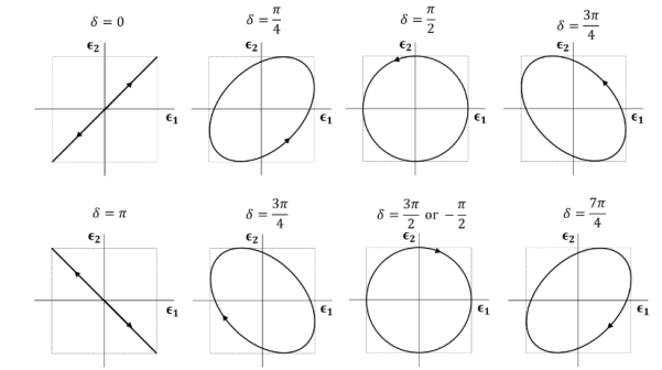
, is again linearly polarized.Elliptically polarized waveIf E1 and E2 have different phases, the wave of Eq. 7.27 is elliptically polarized. The simplest case is circular polarization. Then a1 = a2 and
 :
: At a fixed point in space, the fields are such that the electric vector is constant in magnitude, but sweeps around in a circle at a frequency ω, as shown in Figure For
  +=
+=  , the tip of the E-vector traces the circular path counter clockwise. This wave is called left circularly polarized (positive helicity) in optics. For
  ,
, ), same path but traced clockwise, then the wave is called right circularly polarized (negative helicity). For other values of
  , we have elliptical polarization for the trace being an ellipse.
Figure 4: Trace of the tip of the E-vector (a1 = a2) at a given point in space as a function of time. The propagation direction is point toward us. The traces for  and
and  are linearly polarized. The traces for
  and
and  are left and right circularly polarized, respectively. Q4) If the electric field strength of a radio broadcast signal at a TV receiver is given by E = 5.0 cos (t-y) az, V/m,Determine the displacement current density. If the same field exists in a medium whose conductivity is given by 2.0 x 10³(mho)/cm, find the conduction current density.A4) E at a TV receiver in free space= 5.0 cos (t-y) az, V/m Electric flux density D =0E = 50cos (t-y) az, V/mThe displacement current densityJd =
  =
=  Jd=-50sin (t-y) az, V/m2The conduction current density,Jc =E=2.0 x 10³(mho) /cm= 2 x 10⁵mho /mJc= 2 x 105x 5 cos (t-y) azJc= 106cos (t-y) az V/m2 Q5) Given E = 10 sin (t-y) ay V/m, in free space, determine D, B and H.A5) E = 10 sin (t-y) ay, V/mD =0E,0= 8.854 x 10⁻¹² F/mD = 100sin (t-y) ay, C/m2Second Maxwell’s equation isx E = -BThat is,
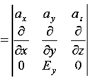
As Ey= 10 sin (t-z) V/m = 0Now,x E becomesx E = -
  ax= 10 cos (t-z) ax= -
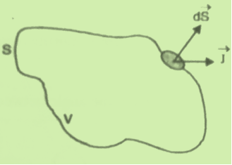
Q6) Discuss continuity equation for current density.A6) Consider a closed surface S enclosing a Volume V through which currents are flowing. Let I be the current passing through the surface at any time t. Consider a small area  of the closed surface. The outward current flowing through
  at a time t is
dI =  …………..(1)the total current flowing out through the closed surface S at time t isI =
  …………..(2)Suppose isρ the Volume Charge density of charges inside the surface S. Then the total charge inside the Volume V is q =
  …………..(3)Since the current is flowing outward is it mean that charge within the enclosed surface is decreasing with time. The time rate of decrease of charge is
 = -
= - …………..(4)The negative sign shows that the charge inside the surface S is decreasing with time. The above equation can be written as
 = -
= -  …………..(5)Since the charge is conserved, the current flowing outward through the closed surface must be equal to the rate of decrease of charge. Thus I =
  Using equation (2) and (5), it becomes
 = -
= -  …………..(6)According to divergence theorem
  =
=  dVUsing this result in equation (6) we obtain
 dV = -
  This equation holds good for arbitrary volumes. Therefore the integrands must be equal. Hence
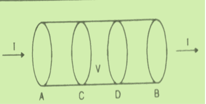
 =0 …………..(7)This equation is called equation of continuity. It is the mathematical statement of law of conservation of charge. SPECIAL CASEConsider a conductor AB through which a steady current I is flowing. The current I is said to be steady if charge is flowing per unit time through any two any sections C and D is the same. This means that the total amount of charge entering the volume V through C is equal to the charge leaving the volume V through D. Thus there is no change in the volume charge density in the volume V with time i.e.
 =0
=0
We may define steady current as that current in which the charge density is independent of time.Using equation (7) we obtain This is known as the equation of continuity for steady currents.Q7) If the electric field strength, E of an electromagnetic wave in free space is given by E = 2 cos (t -
  ) ay V/m,Find the magnetic field, HA7) We have
Q8) A parallel-plate capacitor with plate area of 5 cm2and plate separations of 3 mm has a voltage 50 sin 103t V applied to its plates. Calculate the displacement current assuming = 20.A8) D =EJd =  =
= Hence,Id = Jd. S =
  =
=  which is the same as the conduction current, given by
= 147.4 cos 103t nAQ9) Write a note on displacement current?A9) Displacement current is the rate of change of electric displacement field.The type of current which passes through a conductor is known as conduction current and is caused by the actual movement of electrons through the conductor. This type of current is mostly used in our day to day life. There is also another kind of current, which is known as displacement current. Displacement current differs from the conduction current because the displacement current does not involve electrons' movement. The displacement current has enormous importance for the propagation of electromagnetic waves. In electromagnetism, displacement current is a quantity appearing in Maxwell's equations that is defined in terms of the rate of change of electric displacement field. Displacement current has the units of electric current density, and it has an associated magnetic field just as actual currents do.It is mathematically represented as ID = JD S = S  Where S = Area of the plate of the capacitor ID = Displacement currentJD = Displacement current densityD = εE where ε is permittivity of the mediumDuring the charging and discharging process of the capacitor, the electric current flows through the wires of the circuit. However, no current flow between the plates of the capacitor. Q10) For a long solenoid the magnetic field strength within the solenoid is given by the equation B=5.0t T, where t is time in seconds. If the induced electric field outside the solenoid is 11 V/m a distance 2.0 m from the axis of the solenoid, find the radius of the solenoid. A10) Given When there is a changing magnetic field through a coil, it causes an induced emf in the coil, which is based on the Faraday's law of electromagnetic induction. Further, the induced emf is related to the induced electric field along the circumference of the coil.Magnetic field inside the solenoid, B =5.0×t T Induced electric field at radial distance (from the axis of solenoid) r = 2.0 m is E =11 V/mRadius (R) of solenoid =?The induced electric field at the radial distance r from the axis of the solenoid is expressed as: E×(2πr) =
 E×(2πr) =
 E×(2×r) =R2
 E×(2×r) = R2
 11×(2×2) =R2×5R=2.966
  3.0 mQ11) A coil has 1000 turns and 500 cm2 as it's area. The plane of the coil is placed at right angles to a magnetic induction field of 2×10⁻⁵ Wb/m2. The coil is rotated through 1800 in 0.2 seconds. What is the average emf induced in the coil (in milli volts)?A11) The induced emf will be given by
emf=
=
=
=
=10×10−3V=10 mVQ12) In a uniform magnetic field of induction B, a wire in the form of semicircle of radius r rotates about the diameter of the circle with angular velocity ω. If the total resistance of the circuit is R, then find the mean power generated per period of rotation.
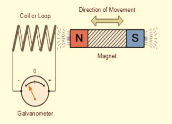
Figure A12) Q13) Question: Discuss Faraday’s law of electromagnetic induction? A13) Faraday’s law of electromagnetic induction (referred to as Faraday’s law) is a basic law of electromagnetism predicting how a magnetic field will interact with an electric circuit to produce an electromotive force (EMF). This phenomenon is known as electromagnetic induction.Faraday’s law states that a current will be induced in a conductor which is exposed to a changing magnetic field. Lenz’s law of electromagnetic induction states that the direction of this induced current will be such that the magnetic field created by the induced current opposes the initial changing magnetic field which produced it. The direction of this current flow can be determined using Fleming’s right-hand rule.Let us understand Faraday’s law by faraday‘s experiment.FARADAY’S EXPERIMENTIn this experiment, Faraday takes a magnet and a coil and connects a galvanometer across the coil. At starting, the magnet is at rest, so there is no deflection in the galvanometer i.e. the needle of the galvanometer is at the center or zero position. When the magnet is moved towards the coil, the needle of the galvanometer deflects in one direction.
Figure 9When the magnet is held stationary at that position, the needle of galvanometer returns to zero position. Now when the magnet moves away from the coil, there is some deflection in the needle but opposite direction, and again when the magnet becomes stationary, at that point respect to the coil, the needle of the galvanometer returns to the zero position. Similarly, if the magnet is held stationary and the coil moves away, and towards the magnet, the galvanometer similarly shows deflection. It is also seen that the faster the change in the magnetic field, the greater will be the induced EMF or voltage in the coil.Let us take a look at the following table. This table is showing the observation of faraday’s experiment.
CONCLUSION From this experiment, Faraday concluded that whenever there is relative motion between a conductor and a magnetic field, the flux linkage with a coil changes and this change in flux induces a voltage across a coil.Michael Faraday formulated two laws on the basis of the above experiments. These laws are called Faraday’s laws of electromagnetic induction.FARADAY’S FIRST LAWAny change in the magnetic field of a coil of wire will cause an emf to be induced in the coil. This emf induced is called induced emf and if the conductor circuit is closed, the current will also circulate through the circuit and this current is called induced current.
Method to change the magnetic field:By moving a magnet towards or away from the coil By moving the coil into or out of the magnetic field By changing the area of a coil placed in the magnetic field By rotating the coil relative to the magnet FARADAY’S SECOND LAWIt states that the magnitude of emf induced in the coil is equal to the rate of change of flux that linkages with the coil. The flux linkage of the coil is the product of the number of turns in the coil and flux associated with the coil.According to Faraday’s law of electromagnetic induction, the rate of change of flux linkage is equal to induced emf. ………..(9)Considering Lenz’s LawWhere:
Flux Φ in Wb = B.A B = magnetic field strength A = area of the coil FACTORS ON WHICH INDUCED EMF DEPENDBy increasing the number of turns in the coil i.e. N, from the formulae derived above it is easily seen that if the number of turns in a coil is increased, the induced emf also gets increased. By increasing magnetic field strength i.e. B surrounding the coil- Mathematically, if magnetic field increases, flux increases and if flux increases emf induced will also get increased. Theoretically, if the coil is passed through a stronger magnetic field, there will be more lines of force for the coil to cut and hence there will be more emf induced. By increasing the speed of the relative motion between the coil and the magnet – If the relative speed between the coil and magnet is increased from its previous value, the coil will cut the lines of flux at a faster rate, so more induced emf would be produced. Q14) Derive relation for displacement current?A14) DerivationAccording to Ampere's law, the magnetic field should not present between the plates as there is no current, but in reality, the magnetic field exists there. Maxwell formulated this limitation of Ampere's law by adding a term in the equation of Ampere's law to solve the issue. Maxwell predicted that the magnetic field will still exist even in the absence of conduction current, and the magnetic field may be associated with the changing electric field. This theory of Maxwell was experimentally proved.Ampere's Law tells us that a flowing electric current gives rise to a magnetic field that circles the wire. In addition to this, it also says that an Electric Field that is changing in time gives rise to a magnetic field that encircles the E-field - this is the Displacement Current term that Maxwell himself introduced. This means there are 2 ways to generate a solenoidal (circulating) H-field - a flowing electric current or a changing Electric Field. Both give rise to the same phenomenon. The modified form of ampere Law is given by H.dL=(J+dD/dt)Take integration on both sides we have∫H.dL=∫(J+dD/dt).dSApply stoke’s theorem to L.H.S. of above equation, we get∫( ∇xH).dS=∫ H.dLNow the above equation is written as∫( ∇xH).dS =∫(J+dD/dt).dSBy cancelling the surface integral on both sides we have ∇xH =J+dD/dtWhich is the differential form of Maxwell’s equation.This can also be written in the form BThe Ampere-Maxwell Law  Begin with the Ampere-Maxwell law in integral form.
Invoke Stokes' theorem.
Set the equation to 0.
 Since the magnetic field is associated with the electric field, the general displacement current formula is given by, ∇
 = μ0 ( J+ε0
 )This equation is the generalized formula of Maxwell-Ampere law. Displacement Current Definition The displacement current (ID or D) is the part which Maxwell has added to the Ampere's law.ID = ε0
 and D = εEε0 = Permittivity of free space The Maxwell equation can be written as ∇
 = μ0 ( J+
 )Q15) What do you meant by gradient? Discuss its physical significance?A15) The gradient is a fancy word for derivative, or the rate of change of a function. It’s a vector (a direction to move) that
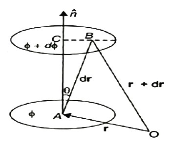
Points in the direction of greatest increase of a function Is zero at a local maximum or local minimum (because there is no single direction of increase) The term "gradient" is typically used for functions with several inputs and a single output (a scalar field). Yes, you can say a line has a gradient (its slope), but using "gradient" for single-variable functions is unnecessarily confusing. Keep it simple.“Gradient” can refer to gradual changes of colour, but we’ll stick to the math definition. You’ll see the meanings are related.PHYSICAL SIGNIFICANCE OF GRADIENTA scalar field may be represented by a series of level surfaces each having a stable value of scalar point function θ. The θ changes by a stable value as we move from one surface to another. These surfaces are known as Gaussian surfaces. Now let the two such surfaces are very close together, be represented by two scalar point functions and (θ + d θ). Let ‘r’ and (r + d θ) be the position vectors of points A and B, on the surfaces θ and (θ + d θ) correspondingly with respect to an origin 0 as shown in Figure. Clearly, the vector AB will be dr. Let the least detachment between the two surfaces ‘dn’ be in the direction of unit usual vector n at A.
9 Figuredn = dr cos θ= | n | dr | cos θ =n .drDϕ = ∂ϕ/ dn =∂ϕ/dn n .dr…… (1)Since the continuous scalar function defining the level surfaces (Gaussian surfaces) has a value θ at point A (x, y, z) and (θ + dθ) at point (x + dx, y + dy, z + dz), we havedϕ = ∂ ϕ/dx dx +dϕ/∂y + ∂ϕ/∂x dz= (I ∂ϕ/∂x +j ∂ϕ/vy +k ∂ϕ/∂z) .(idx +jdy +kdz)= ∆ ϕ. dr … … (2)From equations (1) and (2), equating the values of d θ,We obtain ∆θ .dr =∆ϕ= ∂ϕ/ ∂n n .drAs dr is an arbitrary vector, we have∆ϕ =∂ϕ/∂ nGrad ϕ = ∂ ϕ/∂n nTherefore, the gradient an of a scalar field at any point is a vector field, the scale of which is equal to the highest rate of increase of θ at that point and the direction of it is similar as that of usual to the level surface at that point.Its physical significance of grad can be understand in terms of the graph of some function z = f(x, y), where f is a reasonable function – say with continuous first partial derivatives. In this case we can think of the graph as a surface whose points have variable heights over the xy – plane. An illustration is given below.
10 FigureIf, say, we place a marble at some point (x, y) on this graph with zero initial force, its motion will trace out a path on the surface, and in fact it will choose the direction of steepest descent. This direction of steepest descent is given by the negative of the gradient of f. One takes the negative direction because the height is decreasing rather than increasing.Using the language of vector fields, we may restate this as follows: For the given function f(x, y), gravitational force defines a vector field F over the corresponding surface z = f(x, y), and the initial velocity of an object at a point (x, y) is given mathematically by –∇f(x, y). The gradient also describes directions of maximum change in other contexts. For example, if we think off as describing the temperature at a point(x, y), then the gradient gives the direction in which the temperature is increasing most rapidly.Q16) State Gauss Divergence Theorem ?A16) GAUSS DIVERGENCE THEOREM In vector calculus, divergence theorem is also known as Gauss’s theorem. It relates the flux of a vector field through the closed surface to the divergence of the field in the volume enclosed.The Gauss divergence theorem states that the vector’s outward flux through a closed surface is equal to the volume integral of the divergence over the area within the surface. The sum of all sources subtracted by the sum of every sink will result in the net flow of an area. Gauss divergence theorem is the result that describes the flow of a vector field by a surface to the behaviour of the vector field within it.Let  be a smooth vectorfield defined on a solid region V with boundary surface A oriented outward. Gauss divergence theorem is given by
 The divergence of a vector field F, denoted div(F) or
  (the notation used in this work), is defined by a limit of the surface integral
where the surface integral gives the value of F integrated over a closed infinitesimal boundary surface S= surrounding a volume element V, which is taken to size zero using a limiting process. The divergence of a vector field is therefore a scalar field. If
  =0, then the field is said to be a divergenceless field. The symbol
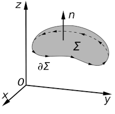
  is variously known as "nabla" or "del." The physical significance of the divergence of a vector field is the rate at which "density" exits a given region of space. The definition of the divergence therefore follows naturally by noting that, in the absence of the creation or destruction of matter, the density within a region of space can change only by having it flow into or out of the region. By measuring the net flux of content passing through a surface surrounding the region of space, it is therefore immediately possible to say how the density of the interior has changed. This property is fundamental in physics, where it goes by the name "principle of continuity." When stated as a formal theorem, it is called the divergence theorem, also known as Gauss's theorem. Q17) State Stokes Theorem?A17) Stokes TheoremStokes Theorem is also referred to as the generalized Stokes Theorem. It is a declaration about the integration of differential forms on different manifolds. It generalizes and simplifies the several theorems from vector calculus. According to this theorem, a line integral is related to the surface integral of vector fields.
Figure 7Stokes’ theorem relates the surface integral of the curl of the vector field to a line integral of the vector field around some boundary of a surface. It is named after George Gabriel Stokes. Although the first known statement of the theorem is by William Thomson and it appears in a letter of his to Stokes.Stoke’s theorem statement is “the surface integral of the curl of a function over the surface bounded by a closed surface will be equal to the line integral of the particular vector function around it.” Stokes theorem gives a relation between line integrals and surface integrals. Depending upon the convenience, one integral can be computed in terms of the other.Stokes Theorem Formula:It is,∮C  = ∬S (∇ ×
 ).
).  Where,C = A closed curve.S = Any surface bounded by C.F = A vector field whose components are continuous derivatives in S.Thus, it means that if we walk in the positive direction around C with our head pointing in the direction of n, then the surface will always be on our left. S is oriented smooth surface bounded by a simple, closed smooth-boundary curve C with positive orientation. It can be noted that the surface S can actually be any surface so long as its boundary curve is given by C. This is something that can be used to our advantage to simplify the surface integral on the occasion.Stokes theorem physics and stokes theorem mathematics are very popular. We can find many applications of stokes theorem in Physics. It helps to derive many useful formulae and equations. For example, stokes theorem in electromagnetic theory is very popular in Physics.Q18) When mean optical power launched into an 8 km length of fibre is 12 μW, the mean optical power at the fibre output is 3 μW. Determine a) Overall signal attenuation in dB.b) The overall signal attenuation for a 10 km optical link using the same fibre with splices at 1 km intervals, each giving an attenuation of 1 dB. A18) Given :z=8kmP(0) = 120 μWP(z) = 3 μW a) Overall attenuation is given by, αp (dB/km )= 10. log
  = 16.02 b) Overall attenuation for 10 km,Attenuation per km = αp (dB/km )=
  =
=  = 2.00 dB/kmAttenuation in 10 km link = 2.00 x 10 = 20 dBIn 10 km link there will be 9 splices at 1 km interval. Each splices introducing attenuation of 1 dB.Total attenuation = 20 dB + 9 dB = 29 dB tr mod = 0.44 (∆tmodal)πr2Q19) Give Physical Significance ofMaxwell’s equation ?A19) Physical significance of Maxwell’s Ist equation∇·E = ρ/ε0According to this total electric flux through any closed surface is 1/0 times the total charge enclosed by the closed surfaces, representing Gauss's law of electrostatics, As this does not depend on time, it is a steady state equation. Here for positive , divergence of electric field is positive and for negative divergence is negative. It indicates that is scalar quantity.Physical significance of Maxwell’s 2nd equation ∇·B = 0It represents Gauss law of magnetostatic as ∇·B = 0 resulting that isolated magnetic poles or magnetic monopoles cannot exist as they appear only in pairs and there is no source or sink for magnetic lines of forces. It is also independent of time i.e. steady state equation.Physical significance of Maxwell’s 3rd equation ∇×E = −∂B/∂t It shows that with time varying magnetic flux, electric field is produced in accordance with Faraday is law of electromagnetic induction. This is a time dependent equation.Physical significance of Maxwell’s 4th equation∇×H = J + ∂D/∂t This is a time dependent equation which represents the modified differential form of Ampere's circuital law according to which magnetic field is produced due to combined effect of conduction current density and displacement current density.Q20) Write down solution for plane electromagnetic waves in vacuum?A20) In an electromagnetic wave, electric and magnetic field vectors are perpendicular to each other and at the same time are perpendicular to the direction of propagation of the wave. This nature of electromagnetic wave is known as Transverse nature.Maxwell proved that both the electric and magnetic fields are perpendicular to each other in the direction of wave propagation. He considered an electromagnetic wave propagating along positive x-axis. When a rectangular parallelepiped was placed parallel to the three co-ordinate axis, the electric and magnetic fields propagate sinusoidal with the x-axis and are independent of y and z-axis.A wave in which the values of variable are constant in a plane perpendicular to the direction of propagation of the wave is called plane wave. These planes may also termed as wave fronts.Solutions of Maxwell’s Equations - Uniform Plane WavesThe sources of time varying electromagnetic fields are time varying charges and currents, whether man-made or naturally occurring. However, examination of Maxwell’s equations shows that, even in empty space (with no sources), and fields cause each other. This means that, although these fields must originate in source regions, they can propagate through source-free regions. Because solutions in source regions are very hard to obtain, let us consider what kind of fields can exist in source-free regions.
These equations are still very complicated (4 different partial derivatives). Let’s try to find simple solutions. We do this by making assumptions. After finding simplest solutions, we:(i) Find what kind of source would generate this type of field (waves).(ii) Show that these simple solutions are useful approximations to real electromagnetic waves.Assumption for Solution: Can we find a solution such that:1.) No variation exists in x and y directions.2.)  or
or  also is oriented along one of the axes.Ampere’s Law becomes:
or, with our assumptions: Compare for transmission line:
 In a similar manner,
  ………….(1)Faraday’s Law becomes:
 ………….(2)Thus, if
  is only in the
  direction, then is only in the .If we differentiate (2) with respect to z, we get:
Substitute from (2), We get
 This is called the wave equation.Compare for transmission line: (same).
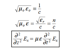
 We will assume dielectric media; lossless:
  Dimensional analysis:
 In the units we are using:
 By exactly the same method, we also get:
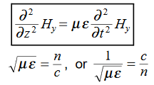 For example, the same equation is true for
  and
and  . Thus,
  and
and  must have the same type of functional dependence. This wave equation still has many possible solutions. In fact, it can be shown by direct substitution that
 are the solutions
 t is important to note that f1 and f2 can be any function.The field we find directly from the equation:
 Suppose
 …………(3)Differentiate (3) with respect to z
  …………(4)Integrate with respect to time
 …………(5)
 This leads to a new quantity that relates the electric and magnetic fields:
 Rewriting:Units of
  =
=  =
=  = Ω
= Ω 0 = Impedance of free space =
  =377Ω
=377Ω = impedance of a lossless dielectric =
  =
= =
=  Note that
  and
and  are in time phase and space quadratureThe directions of the vectors are such that:
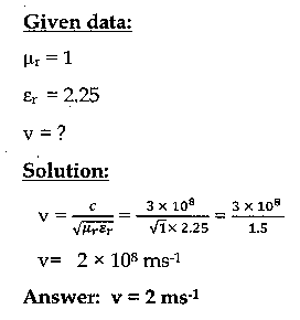
This vector  , always points in the direction of propagation. These types of waves are called Uniform Plane Electromagnetic Waves. “Plane” refers to the fact that, at any instant in time, the surfaces of constant phase are planes (here, constant). “Uniform” means no variation in transverse direction. The wave derived here is one oscillating at a single frequency. The frequency is determined by the source. If the source has multiple frequencies, so will the wave. In communications, modulating a carrier wave results in multiple frequencies. But before we can study such fields, we must thoroughly understand single frequency sinusoidal waves.Q21) If the relative permeability and relative permittivity of the medium is 1.0 and 2.25, respectively. Find the speed of the electromagnetic wave in this medium.A21)
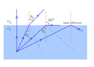
Q22) Discuss Maxwell’s equations ?A22) Maxwell equations are of fundamental importance since they describe the whole of classical electromagnetic phenomena.Maxwell's Equations are a set of 4 complicated equations that describe the world of electromagnetics. These equations describe how electric and magnetic fields propagate, interact, and how they are influenced by objects. Maxwell was one of the first to determine the speed of propagation of electromagnetic (EM) waves was the same as the speed of light - and hence to conclude that EM waves and visible light were really the same thing.These equations are rules the universe uses to govern the behaviour of electric and magnetic fields. A flow of electric current will produce a magnetic field. If the current flow varies with time (as in any wave or periodic signal), the magnetic field will also give rise to an electric field. Maxwell's Equations shows that separated charge (positive and negative) gives rise to an electric field - and if this is varying in time as well will give rise to a propagating electric field, further giving rise to a propagating magnetic field.From a classical perspective, light can be described as waves of electromagnetic radiation. As such, Maxwell equations are very useful to illustrate a number of the characteristics of light including polarization. We are just to stating these equations without derivation. Since our goal is simply to apply them, the usual approach will be followed. Maxwell’s first equation (Gauss' Law for Electric Fields)Gauss' Law is the first of Maxwell's Equations which dictates how the Electric Field behaves around electric charges. Gauss' Law can be written in terms of the Electric Flux Density and the Electric Charge Density as: ∇·E = ρ/ε0 0r∇·D = ρ Hence, Gauss' law is a mathematical statement that the total Electric Flux exiting any volume is equal to the total charge inside. Hence, if the volume in question has no charge within it, the net flow of Electric Flux out of that region is zero. If there is positive charge within a volume, then there exists a positive amount of Electric Flux exiting any volume that surrounds the charge. If there is negative charge within a volume, then there exists a negative amount of Electric Flux exiting (i.e. the Electric Flux enters the volume).Maxwell’s second equation (Faraday's Law)Faraday figured out that a changing Magnetic Flux within a circuit (or closed loop of wire) produced an induced EMF, or voltage within the circuit. Maxwell gives his second equation from this.Faraday's Law tells us that a magnetic field that is changing in time will give rise to a circulating E-field. This means we have two ways of generating E-fields - from Electric Charges (or flowing electric charge, current) or from a magnetic field that is changing.∇×E = −∂B/∂t (2)Maxwell’s third equation (Ampere's Law)Ampere's Law tells us that a flowing electric current gives rise to a magnetic field that circles the wire. In addition to this, it also says that an Electric Field that is changing in time gives rise to a magnetic field that encircles the E-field - this is the Displacement Current term that Maxwell himself introduced. This means there are 2 ways to generate a solenoidal (circulating) H-field - a flowing electric current or a changing Electric Field. Both give rise to the same phenomenon. The modified form of Ampere's Law s given by Maxwell’s third equation∇×H = J + ∂D/∂t Maxwell’s four equation (Gauss' Magnetism law)we know that Gauss' Law for Electric Fields states that the divergence of the Electric Flux Density D is equal to the volume electric charge density. But the second equation, Gauss' Magnetism law states that the divergence of the Magnetic Flux Density (B) is zero. Why? Why isn't the divergence of B equal to the magnetic charge density? Well - it is. But it just so happens that no one has ever found magnetic charge - not in a laboratory or on the street or on the subway. And therefore, until this hypothetical magnetic charge is found, we set the right side of Gauss' Law for Magnetic Fields to zero: ∇·B = 0 Now, you may have played with magnets when you were little, and these magnetic objects attracted other magnets similar to how electric charges repel or attract like electric charges. However, there is something special about these magnets - they always have a positive and negative end. This means every magnetic object is a magnetic dipole, with a north and South Pole. No matter how many times you break the magnetic in half, it will just form more magnetic dipoles. Gauss' Law for Magnetism states that magnetic monopoles do not exist - or at least we haven't found them yet.Maxwell’s four equations are given by∇·E = ρ/ε0 (1)∇×E = −∂B/∂t (2)∇×H = J + ∂D/∂t (3)∇·B = 0 (4)These equations illustrate the unique coexistence in nature of the electric field and the magnetic field. The first two equations give the value of the given flux through a closed surface, and the second two equations give the value of a line integral around a loop. In this notation,∇=(∂/∂x, ∂/∂y, ∂/∂z)E is the electric vectorB is the magnetic inductionρ is the electric charge density j is the electric current densityε0 is the permittivity of free spacec is the speed of light. In addition to Maxwell equations, the following identities are useful: J = σE (5)D = εE (6)B = μH (7) Here,D is the electric displacement H is the magnetic vectorσ is the specific conductivityε is the dielectric constant (or permittivity) μ is the magnetic permeabilityQ23) Discuss the principle, construction, and working of Optical Fibre? A23) A cable that is used to transmit the data through fibres (threads) or plastic (glass) is known as an optical fibre cable. This cable includes a pack of glass threads that transmits modulated messages over light waves. Principle: Optical Fibre works on the principle of Total Internal Reflection.Total internal reflection:- When the light ray travels from a denser medium to a rarer medium the refracted ray bends away from the normal. When the angle of incidence is greater than the critical angle, the refracted ray again reflects into the same medium. This phenomenon is called total internal reflection. The refracted ray bends towards the normal as the ray travels from a rarer medium to a denser medium. The refracted ray bends away from the normal as it travels from denser medium to rarer medium.
Figure – Total Internal Reflection Characteristics of Optical FibreIt has a large bandwidth. The optical frequency of 2 x 10¹⁴ Hz can be used and hence the system has higher bandwidth. Thus optical fibres have greater information-carrying capacity due to greater bandwidth. In an optical fibre system transmission losses are as low as 0.1 db/km. Optical fibre is of small size and lightweight as compared to electrical fibre. Optical fibre communication is free from electromagnetic interference. Optical fibre does not carry high voltage and current hence they are safer than electrical cable. Optical Fibre is flexible and has high tensile strength. Thus can be bent or twisted easily.
Figure: Optical FibreConstruction of Optical Fibre:It consists of a very thin fibre of silica or glass or plastic of a high refractive index called the core. The core has a diameter of 10 um to 100 um. The core is enclosed by a cover of glass or plastic called cladding. The refractive index of the cladding is less than that of the core (which is a must condition for the working of the optical fibre). The difference between the two indicates is very small of order 10-3. The core and the cladding are enclosed in an outer protective jacket made of plastic to provide strength to the optical fibre. The refractive index can change from core to cladding abruptly (as in step-index fibre) or gradually (as in graded-index fibre).
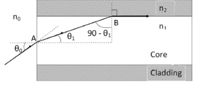
Figure Representation of Optical FibreWorking of Optical FibreWhen a ray of light is incident on the core of the optical fibre at a small angle, it suffers refraction and strikes the core-cladding interface, As the diameter of the fibre is very small hence the angle of incidence is greater than the critical angle. Therefore, the ray suffers total internal reflection at the core-cladding interface and strikes the opposite interface. At this interface also, the angle of incidence is greater than the critical angle, so it again suffers total internal reflection. Thus, the ray of light reaches the other end of the fibre after suffering repeated total internal reflections along the length of the fibre. At the other end, the ray suffers refraction and emerges out of the optical fibre. We can see that the light travels in the core in a guided manner. Hence the communication through the optical fibre is sometimes referred to as an optical waveguide.Q24) Explain the terms acceptance angle, acceptance cone, numerical aperture.or Derive expressions for the numerical aperture and fraction change in refractive index change of an optical fibre. A24) Acceptance angle Definition:-Acceptance angle is defined as the maximum angle of incidence at the interface of air medium and core medium for which the light ray enters into the core and travels along with the interface of core and cladding. Let n0 be the refractive indices of airn1 be the refractive indices of coren2 be the refractive indices of cladding
Let a light ray OA is an incident on the interface of air medium and core medium with an angle of incidence θ0The light ray refracts into the core medium with an angle of refraction θ1 and the refracted ray AB is again incident on the interface of core and cladding with an angle of the incident (90-θ1) If (90-θ1) is equal to the critical angle of core and cladding media then the ray travels along with the interface of core and cladding along the path BC. If the angle of the incident at the interface of air and coreθ1<θ0 then (90-θ1) will be greater than the critical angle. Therefore, The total internal reflection takes place.According to Snell’s law at point An0 Sin θ0 = n1 Sin θ1Sin θ0= (n1 / n0) Sin θ1 ………(1)According to Snell’s law at point Bn1 Sin(90- θ1) = n2 Sin90 ………(2)n1 Cosθ1 = n2 as(Sin90=1)Cosθ1 = n2 /n1Sinθ1 = (1-Cos2θ1)1/2Sinθ1= (1- (n2 /n1)2)1/2Sinθ1= ( n12- n22 )1/2/ n1 ………(3)We know Sin θ0= (n1 / n0) Sin θ1 from equation (1)Substitute the value of Sinθ1 from equation (3)Sinθ0= (n1 / n0) *( n12- n22 )1/2/ n1On simplificationSinθ0= ( n12- n22 )1/2/ n0θ0=Sin-1( n12- n22 )1/2/ n0 Acceptance Angle is θ0=Sin-1( n12- n22 )1/2/ n0 ………(4)Acceptance ConeAcceptance angle is the maximum angle that a light ray can have relative to the axis of the fibre and propagate down the fibre. Thus, only those rays that are incident on the face of the fibre making angles less than θ0 will undergo repeated total internal reflections and reach the other end of the fibre. Hence, larger acceptance angles make it easier to launch light into fibre.
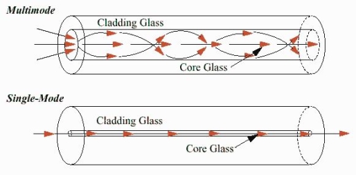
Figure: 27In three dimensions, the light rays contained within the cone having a full angle 2θ0 are accepted and transmitted along with the fibre as shown in figure 27. Therefore, the cone is called the acceptance cone. Light incident at an angle beyond θ0 refracts through the cladding and corresponding optical energy is lost.Numerical apertureDefinition: -Numerical aperture is defined as the light gathering capacity of an optical fibre and it is directly proportional to the acceptance angle. Numerically it is equal to the sin of the acceptance angle.NA = Sin(acceptance angle)NA = Sin {Sin-1(( n12- n22 )1/2/ n0)} from equation (4)NA = (( n12- n22 )1/2/ n0) ………(5)If the refractive index of the air medium is unity i.e. n0=1 put in (5)NA = ( n12- n22 )1/2 ………(6)Fractionalchange in refractive index∆= (n1- n2)/ n1n1∆ = (n1- n2) ………(7)from equation (6), we haveNA = {( n1- n2 )( n1+n2 )}1/2NA = { n1∆ (n1+n2 )}1/2 as n1∆ = (n1- n2) by Eq(7)NA = { n1∆ 2n1}1/2 n1≈n2, so n1+n2 =2n1NA = n1{2∆}1/2 This gives the relation between Numerical aperture and Fractionalchange in refractive index.Q25) What are the advantages and disadvantages of an optical fibre?A25) Advantages of fibre optic communication Optical fibre communication has more advantages than conventional communication. 1. Enormous Bandwidth 2. Low Transmission Loss 3. Electric Isolation 4. Signal Security5. Small Size and Less Weight6. Immunity Cross Talk 1. Enormous bandwidth:- The information-carrying capacity of a transmission system is directly proportional to the frequency of the transmitted signals. In the coaxial cable transmission, the bandwidth range is up to around 500MHz only. Whereas in optical fibre communication, the bandwidth range is large as 105 GHz. 2. Low transmission loss:- The transmission loss is very low in optical fibres (i.e.KmdB/2.0) than compare with the conventional communication system. Hence for long-distance communication fibres are preferred. 3. Electric isolation:- Since fibre optic materials are insulators, they do not exhibit earth and interface problems. Hence communicate through fibre even in an electrical dangerous environment. 4. Signal security:- The transmitted signal through the fibre does not radiate, unlike the copper cables, a transmitted signal cannot be drawn from fibre without tampering with it. Thus the optical fibre communication provides 100% signal security. 5. Small size and less weight:- The size of the fibre ranges from 10μm to 50μm, which is very small. The space occupied by the fibre cable is negligibly small compared to conventional electrical cables. Optical fibres are light in weight. 6. Immunity cross-talk:- Since the optical fibres are dielectric waveguides, they are free from any electromagnetic interference and radio frequency interference. Since optical interference among different fibres is not possible, cross talk is negligible even many fibres are cabled together. Disadvantages of Optical FibreThe disadvantages of optical fibre include the followingThe main disadvantages of these cables are installation is expensive and difficult to fix together. The optical fibre cables are very difficult to merge & there will be a loss of the beam within the cable while scattering. Fibre optic cables are compact and highly vulnerable while fitting These cables are more delicate than copper wires. Special devices are needed to check the transmission of fibre cables. Q26) Explain how the optical fibres are classified?A26) TYPES OF OPTICAL FIBRESThe types of optical fibres depend on the refractive index, materials used, and mode of propagation of light.The classification based on the materials used is as follows: Plastic Optical Fibres: The polymethylmethacrylate is used as a core material for the transmission of light. Example: Core: polymethyl methacrylate : Cladding: Co- PolymerCore: Polystyrene : Cladding: Methyl methacrylate Glass Fibres: It consists of extremely fine glass fibres. Example: Core: SiO2 Cladding: SiO2Core: GeO2- SiO2 Cladding: SiO2The classification based on the mode of propagation of light is as follows: Mode of propagation:Light propagates as electromagnetic waves through an optical fibre. All waves, having ray directions above the critical angle will be trapped within the fibre due to total internal reflection. However, all such waves do not propagate through the fibre. Only certain ray directions are allowed to propagate. The allowed directions correspond to the modes of the fibre. In simple terms, modes can be visualized as the possible number of paths of light in an optical fibre. Single-Mode Fibres: These fibres are used for long-distance transmission of signals. In general, the single mode fibres are step-index fibres. These types of fibres are made from doped silica. It has a very small core diameter so that it can allow only one mode of propagation and hence called single-mode fibres.The cladding diameter must be very large compared to the core diameter. Thus in the case of single-mode fibre, the optical loss is very much reduced. The structure of a single-mode fibre is given below.Structure:Core diameter : 5-10μmCladding diameter : Generally around 125μmProtective layer : 250 to 1000μmNumerical aperture : 0.08 to 0.10Bandwidth : More than 50MHz km.Application:Because of high bandwidth, they are used in long-haul communication systems.
Multimode Fibres:
 and
and  of an em plane wave with space and time.Variation With SpaceFirst we will consider the variation with space. Suppose a plane em wave is propagating along x axis. Then the values of the field vectors
  and
and  will be constant on any plane parallel to YZ plane. That is: For
 =
= =
= =
= = 0 …………(1)For
 =
= =
= =
= = 0 …………(2)From Maxwell’s equation for free space, we have∇.E=0 Therefore
  +
+ +
+ =0Which gives
 =0 …………(3) Also From Maxwell’s equation for free space, we have ∇.B=0 we have ∇.H=0 as B = μH Hence
 +
+ +
+ =0Which gives
 =0 …………(4)The equation (3) and (4) show that there is no variation of
  and
and  along the X axis. In other words, there is no variation in the longitudinal component of
  and
and  .Time Variation of
  and
and  The Maxwell’s equation in free space can be written as:∇ x E= -dB/dt or ∇ x E= -μ
 because B = μH Comparing the rectangular components, we find:
 -
-  = -μ
= -μ …………(5)
 -
-  = -μ
= -μ …………(6)
 -
-  = -μ
= -μ …………(7)Applying the condition listed in equation (1), from equation (5), we find:
 -
-  =0
=0 =0 …………(8)Again using Maxwell’s equation for free space is:∇ x H=
  = Ɛ
= Ɛ Comparing the rectangular components, we can write:
 -
-  = Ɛ
= Ɛ …………(9)
 -
-  = Ɛ
= Ɛ …………(10)
 -
-  = Ɛ
= Ɛ …………(11)Again using the conditions listed in equation (2) gives:
 -
-  = 0
= 0 = 0 …………(12)From equation (8) and (12), we find that there is no variation in the values of
  and
and  with time. That is
  and
and  neither vary with space nor with time. So at the most they can have constant value. But the constant values of
  and
and  contribute nothing towards the wave because for the wave the field vectors must possess oscillatory nature. This shows that there is no longitudinal component of the field vectors in the electromagnetic wave. In other words, for the purpose of discussing of the wave nature, we may put
  =0Now from equation 6 and 7 by putting
  = 0, we find:
 = μ
= μ …………(13)
 = - μ
= - μ …………(14)Similarly putting
  =0 in equation (10) and (11) we find:
 = - Ɛ
= - Ɛ …………(10)
 = Ɛ
= Ɛ …………(11)These relations show that in the em values
  and
and  are related to each other. Also
  and
and  are related to each other, and their time or space variation are not zero. From this we conclude that the em wave is transverse in nature. Q2) Derive electromagnetic wave equation?A2) Wave is nothing but a pattern of disturbance which propagates and carry energy with it. You can produce a wave on a rope by moving one end of the rope up and down. The wave produces on rope needs a medium to propagate and here medium is rope itself. This type of waves is known as mechanical waves. But in the case of Electromagnetic waves, they don't need a medium to propagate. Electromagnetic waves are waves that are created as a result of variations of electric field and a magnetic field. Or we can say that Electromagnetic waves are nothing but changing magnetic and electric fields. Electromagnetic waves are also known to be solutions of Maxwell's equations. And Maxwell's equations are the fundamental equations of electrodynamics. Electromagnetic waves can transmit energy and travel through a vacuum. Light waves are examples of electromagnetic waves. Generally, Electromagnetic waves are shown by a sinusoidal graph.
|
 (x,t) traveling in the x direction with speed v. Equating the speed with the coefficients, we derive the speed of electric and magnetic waves, which is a constant that we symbolize with “c”It is useful to note that in vacuumc2=1/ε0μ0 Where μ0 is the permeability of free space
 Let us rewrite the equation (20) and (21) for one dimension.Or d 2 E/dx2 = μ0ε0 d 2 E/dt2 (22)d2H/dx2 = μ0ε0 d2H/dt2 (23)The simplest solutions to the differential equations (22) and (23) are sinusoidal wave functions:E(x) = Emax cos(kx-t) (24)B(x) = Bmax cos(kx-t) (25)where k = 2π/λ is the wavenumber ,ω = 2πƒ is the angular frequency, λ is the wavelength, f is the frequency and ω /k=f=v= c. Q3) Discuss the polarization of em wave? A3) There is more to be said about the complex vector amplitudes Ɛ and B. We introduce a right-handed set of orthogonal unit vectors (Ɛ1, Ɛ2, n), as shown in Figure, where we take n to be the propagation direction of the plane wave. In general, the electric field amplitude Ɛ can be written as
  where the amplitudes and are arbitrary complex numbers. The two plane waves
 and
and if the n index of refraction is real, Ɛ and B have the same phase) are said to be linearly polarized with polarization vectors Ɛ1andƐ2 .Thus the most general homogeneous plane wave propagating in the direction k=kn is expressed as the superposition of two independent plane waves of linear polarization:
| |
| |
 Then, for example,
 that is
  1 is the phase of the E-field component in the Ɛ1-direction. It is no restriction to let
 2
2 1
1  1=0Since
  1=0 merely dictates a certain choice of the origin of t. With this choice,
|
|
 , that is, at any given point x, the maximum of E in the Ɛ1-direction may be attained at a different time from the maximum E of in the –direction Ɛ2.A detailed picture of the oscillating E-field at a certain point , e.g. x=0,, is best seen by considering some special cases.
|
 , i.e.,
  represents a linearly polarized wave, with its polarization vector Ɛ= Ɛ1cosθ+Ɛ2sinθwith θ=tan-1 (a2/a1)and a magnitude E=
 as shown in Figure.
|
 ,
, is again linearly polarized.Elliptically polarized waveIf E1 and E2 have different phases, the wave of Eq. 7.27 is elliptically polarized. The simplest case is circular polarization. Then a1 = a2 and
 :
: At a fixed point in space, the fields are such that the electric vector is constant in magnitude, but sweeps around in a circle at a frequency ω, as shown in Figure For
  +=
+=  , the tip of the E-vector traces the circular path counter clockwise. This wave is called left circularly polarized (positive helicity) in optics. For
  ,
, ), same path but traced clockwise, then the wave is called right circularly polarized (negative helicity). For other values of
  , we have elliptical polarization for the trace being an ellipse.
|
 and
and  are linearly polarized. The traces for
  and
and  are left and right circularly polarized, respectively. Q4) If the electric field strength of a radio broadcast signal at a TV receiver is given by E = 5.0 cos (t-y) az, V/m,Determine the displacement current density. If the same field exists in a medium whose conductivity is given by 2.0 x 10³(mho)/cm, find the conduction current density.A4) E at a TV receiver in free space= 5.0 cos (t-y) az, V/m Electric flux density D =0E = 50cos (t-y) az, V/mThe displacement current densityJd =
  =
=  Jd=-50sin (t-y) az, V/m2The conduction current density,Jc =E=2.0 x 10³(mho) /cm= 2 x 10⁵mho /mJc= 2 x 105x 5 cos (t-y) azJc= 106cos (t-y) az V/m2 Q5) Given E = 10 sin (t-y) ay V/m, in free space, determine D, B and H.A5) E = 10 sin (t-y) ay, V/mD =0E,0= 8.854 x 10⁻¹² F/mD = 100sin (t-y) ay, C/m2Second Maxwell’s equation isx E = -BThat is,
or
|
 = 0Now,x E becomesx E = -
  ax= 10 cos (t-z) ax= -
|
|
 of the closed surface. The outward current flowing through
  at a time t is
|
 …………..(1)the total current flowing out through the closed surface S at time t isI =
  …………..(2)Suppose isρ the Volume Charge density of charges inside the surface S. Then the total charge inside the Volume V is q =
  …………..(3)Since the current is flowing outward is it mean that charge within the enclosed surface is decreasing with time. The time rate of decrease of charge is
 = -
= - …………..(4)The negative sign shows that the charge inside the surface S is decreasing with time. The above equation can be written as
 = -
= -  …………..(5)Since the charge is conserved, the current flowing outward through the closed surface must be equal to the rate of decrease of charge. Thus I =
  Using equation (2) and (5), it becomes
 = -
= -  …………..(6)According to divergence theorem
  =
=  dVUsing this result in equation (6) we obtain
 dV = -
  This equation holds good for arbitrary volumes. Therefore the integrands must be equal. Hence
 =0 …………..(7)This equation is called equation of continuity. It is the mathematical statement of law of conservation of charge. SPECIAL CASEConsider a conductor AB through which a steady current I is flowing. The current I is said to be steady if charge is flowing per unit time through any two any sections C and D is the same. This means that the total amount of charge entering the volume V through C is equal to the charge leaving the volume V through D. Thus there is no change in the volume charge density in the volume V with time i.e.
 =0
=0
|
 This is known as the equation of continuity for steady currents.Q7) If the electric field strength, E of an electromagnetic wave in free space is given by E = 2 cos (t -
  ) ay V/m,Find the magnetic field, HA7) We have
 B/t =-x E
Thus
Also
|
 =
= Hence,Id = Jd. S =
  =
=  which is the same as the conduction current, given by
|
|
 Where S = Area of the plate of the capacitor ID = Displacement currentJD = Displacement current densityD = εE where ε is permittivity of the mediumDuring the charging and discharging process of the capacitor, the electric current flows through the wires of the circuit. However, no current flow between the plates of the capacitor. Q10) For a long solenoid the magnetic field strength within the solenoid is given by the equation B=5.0t T, where t is time in seconds. If the induced electric field outside the solenoid is 11 V/m a distance 2.0 m from the axis of the solenoid, find the radius of the solenoid. A10) Given When there is a changing magnetic field through a coil, it causes an induced emf in the coil, which is based on the Faraday's law of electromagnetic induction. Further, the induced emf is related to the induced electric field along the circumference of the coil.Magnetic field inside the solenoid, B =5.0×t T Induced electric field at radial distance (from the axis of solenoid) r = 2.0 m is E =11 V/mRadius (R) of solenoid =?The induced electric field at the radial distance r from the axis of the solenoid is expressed as: E×(2πr) =
 E×(2πr) =
 E×(2×r) =R2
 E×(2×r) = R2
 11×(2×2) =R2×5R=2.966
  3.0 mQ11) A coil has 1000 turns and 500 cm2 as it's area. The plane of the coil is placed at right angles to a magnetic induction field of 2×10⁻⁵ Wb/m2. The coil is rotated through 1800 in 0.2 seconds. What is the average emf induced in the coil (in milli volts)?A11) The induced emf will be given by
emf=

=

=

=

=10×10−3V=10 mVQ12) In a uniform magnetic field of induction B, a wire in the form of semicircle of radius r rotates about the diameter of the circle with angular velocity ω. If the total resistance of the circuit is R, then find the mean power generated per period of rotation.
|
 Q13) Question: Discuss Faraday’s law of electromagnetic induction? A13) Faraday’s law of electromagnetic induction (referred to as Faraday’s law) is a basic law of electromagnetism predicting how a magnetic field will interact with an electric circuit to produce an electromotive force (EMF). This phenomenon is known as electromagnetic induction.Faraday’s law states that a current will be induced in a conductor which is exposed to a changing magnetic field. Lenz’s law of electromagnetic induction states that the direction of this induced current will be such that the magnetic field created by the induced current opposes the initial changing magnetic field which produced it. The direction of this current flow can be determined using Fleming’s right-hand rule.Let us understand Faraday’s law by faraday‘s experiment.FARADAY’S EXPERIMENTIn this experiment, Faraday takes a magnet and a coil and connects a galvanometer across the coil. At starting, the magnet is at rest, so there is no deflection in the galvanometer i.e. the needle of the galvanometer is at the center or zero position. When the magnet is moved towards the coil, the needle of the galvanometer deflects in one direction.
|
Position of magnet | Deflection in galvanometer |
Magnet at rest | No deflection in the galvanometer |
Magnet moves towards the coil | Deflection in galvanometer in one direction |
Magnet is held stationary at same position (near the coil) | No deflection in the galvanometer |
Magnet moves away from the coil | Deflection in galvanometer but in the opposite direction |
Magnet is held stationary at the same position (away from the coil) | No deflection in the galvanometer |
Method to change the magnetic field:
 ………..(9)Considering Lenz’s LawWhere:
 Begin with the Ampere-Maxwell law in integral form.
|
|

 Since the magnetic field is associated with the electric field, the general displacement current formula is given by, ∇
 = μ0 ( J+ε0
 )This equation is the generalized formula of Maxwell-Ampere law. Displacement Current Definition The displacement current (ID or D) is the part which Maxwell has added to the Ampere's law.ID = ε0
 and D = εEε0 = Permittivity of free space The Maxwell equation can be written as ∇
 = μ0 ( J+
 )Q15) What do you meant by gradient? Discuss its physical significance?A15) The gradient is a fancy word for derivative, or the rate of change of a function. It’s a vector (a direction to move) that
|
|
 be a smooth vectorfield defined on a solid region V with boundary surface A oriented outward. Gauss divergence theorem is given by
 The divergence of a vector field F, denoted div(F) or
  (the notation used in this work), is defined by a limit of the surface integral
| (1) |
 surrounding a volume element V, which is taken to size zero using a limiting process. The divergence of a vector field is therefore a scalar field. If
  =0, then the field is said to be a divergenceless field. The symbol
  is variously known as "nabla" or "del." The physical significance of the divergence of a vector field is the rate at which "density" exits a given region of space. The definition of the divergence therefore follows naturally by noting that, in the absence of the creation or destruction of matter, the density within a region of space can change only by having it flow into or out of the region. By measuring the net flux of content passing through a surface surrounding the region of space, it is therefore immediately possible to say how the density of the interior has changed. This property is fundamental in physics, where it goes by the name "principle of continuity." When stated as a formal theorem, it is called the divergence theorem, also known as Gauss's theorem. Q17) State Stokes Theorem?A17) Stokes TheoremStokes Theorem is also referred to as the generalized Stokes Theorem. It is a declaration about the integration of differential forms on different manifolds. It generalizes and simplifies the several theorems from vector calculus. According to this theorem, a line integral is related to the surface integral of vector fields.
|
 = ∬S (∇ ×
 ).
).  Where,C = A closed curve.S = Any surface bounded by C.F = A vector field whose components are continuous derivatives in S.Thus, it means that if we walk in the positive direction around C with our head pointing in the direction of n, then the surface will always be on our left. S is oriented smooth surface bounded by a simple, closed smooth-boundary curve C with positive orientation. It can be noted that the surface S can actually be any surface so long as its boundary curve is given by C. This is something that can be used to our advantage to simplify the surface integral on the occasion.Stokes theorem physics and stokes theorem mathematics are very popular. We can find many applications of stokes theorem in Physics. It helps to derive many useful formulae and equations. For example, stokes theorem in electromagnetic theory is very popular in Physics.Q18) When mean optical power launched into an 8 km length of fibre is 12 μW, the mean optical power at the fibre output is 3 μW. Determine a) Overall signal attenuation in dB.b) The overall signal attenuation for a 10 km optical link using the same fibre with splices at 1 km intervals, each giving an attenuation of 1 dB. A18) Given :z=8kmP(0) = 120 μWP(z) = 3 μW a) Overall attenuation is given by, αp (dB/km )= 10. log
  = 16.02 b) Overall attenuation for 10 km,Attenuation per km = αp (dB/km )=
  =
=  = 2.00 dB/kmAttenuation in 10 km link = 2.00 x 10 = 20 dBIn 10 km link there will be 9 splices at 1 km interval. Each splices introducing attenuation of 1 dB.Total attenuation = 20 dB + 9 dB = 29 dB tr mod = 0.44 (∆tmodal)πr2Q19) Give Physical Significance ofMaxwell’s equation ?A19) Physical significance of Maxwell’s Ist equation∇·E = ρ/ε0According to this total electric flux through any closed surface is 1/0 times the total charge enclosed by the closed surfaces, representing Gauss's law of electrostatics, As this does not depend on time, it is a steady state equation. Here for positive , divergence of electric field is positive and for negative divergence is negative. It indicates that is scalar quantity.Physical significance of Maxwell’s 2nd equation ∇·B = 0It represents Gauss law of magnetostatic as ∇·B = 0 resulting that isolated magnetic poles or magnetic monopoles cannot exist as they appear only in pairs and there is no source or sink for magnetic lines of forces. It is also independent of time i.e. steady state equation.Physical significance of Maxwell’s 3rd equation ∇×E = −∂B/∂t It shows that with time varying magnetic flux, electric field is produced in accordance with Faraday is law of electromagnetic induction. This is a time dependent equation.Physical significance of Maxwell’s 4th equation∇×H = J + ∂D/∂t This is a time dependent equation which represents the modified differential form of Ampere's circuital law according to which magnetic field is produced due to combined effect of conduction current density and displacement current density.Q20) Write down solution for plane electromagnetic waves in vacuum?A20) In an electromagnetic wave, electric and magnetic field vectors are perpendicular to each other and at the same time are perpendicular to the direction of propagation of the wave. This nature of electromagnetic wave is known as Transverse nature.Maxwell proved that both the electric and magnetic fields are perpendicular to each other in the direction of wave propagation. He considered an electromagnetic wave propagating along positive x-axis. When a rectangular parallelepiped was placed parallel to the three co-ordinate axis, the electric and magnetic fields propagate sinusoidal with the x-axis and are independent of y and z-axis.A wave in which the values of variable are constant in a plane perpendicular to the direction of propagation of the wave is called plane wave. These planes may also termed as wave fronts.Solutions of Maxwell’s Equations - Uniform Plane WavesThe sources of time varying electromagnetic fields are time varying charges and currents, whether man-made or naturally occurring. However, examination of Maxwell’s equations shows that, even in empty space (with no sources), and fields cause each other. This means that, although these fields must originate in source regions, they can propagate through source-free regions. Because solutions in source regions are very hard to obtain, let us consider what kind of fields can exist in source-free regions.
|
 or
or  also is oriented along one of the axes.Ampere’s Law becomes:
|
 Compare for transmission line:
 In a similar manner,
  ………….(1)Faraday’s Law becomes:
 ………….(2)Thus, if
  is only in the
  direction, then is only in the .If we differentiate (2) with respect to z, we get:
|
 We get
 This is called the wave equation.Compare for transmission line: (same).
 We will assume dielectric media; lossless:
  Dimensional analysis:
 In the units we are using:
 By exactly the same method, we also get:
 For example, the same equation is true for
  and
and  . Thus,
  and
and  must have the same type of functional dependence. This wave equation still has many possible solutions. In fact, it can be shown by direct substitution that
 are the solutions
 t is important to note that f1 and f2 can be any function.The field we find directly from the equation:
 Suppose
 …………(3)Differentiate (3) with respect to z
  …………(4)Integrate with respect to time
 …………(5)
 This leads to a new quantity that relates the electric and magnetic fields:
|
 Rewriting:Units of
  =
=  =
=  = Ω
= Ω 0 = Impedance of free space =
  =377Ω
=377Ω = impedance of a lossless dielectric =
  =
= =
=  Note that
  and
and  are in time phase and space quadratureThe directions of the vectors are such that:
|
 , always points in the direction of propagation. These types of waves are called Uniform Plane Electromagnetic Waves. “Plane” refers to the fact that, at any instant in time, the surfaces of constant phase are planes (here, constant). “Uniform” means no variation in transverse direction. The wave derived here is one oscillating at a single frequency. The frequency is determined by the source. If the source has multiple frequencies, so will the wave. In communications, modulating a carrier wave results in multiple frequencies. But before we can study such fields, we must thoroughly understand single frequency sinusoidal waves.Q21) If the relative permeability and relative permittivity of the medium is 1.0 and 2.25, respectively. Find the speed of the electromagnetic wave in this medium.A21)
|
|
|
|
|
|
|
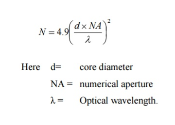
These fibres are used for short-distance transmission of signals. The multi-mode fibres are useful in manufacturing both for step-index and graded-index fibres. The multi-mode fibres are made by multi-component glass compounds such as Glass – Clad Glass, Silica – Clad – Silica, doped silica, etc. Here the core diameter is very large compared to single-mode fibres, so that it can allow many modes to propagate through it and hence called Multi-mode fibres. The cladding diameter is also larger than the diameter of the single-mode fibres. The structure of the multimode fibre is as shown in the figure above.Structure:Core diameter : 50-350μmCladding diameter : 125μm - 500μmProtective layer : 250 to 1100μmNumerical aperture : 0.12 to 0.5Bandwidth : Less than 50MHz km. The total number of modes possible for such an electromagnetic waveguide is
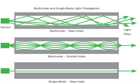
Because of its less bandwidth, it is very useful in short-haul communication systems. The classification based on the refractive index is as follows:Step Index Single-mode Fibres It consists of a core surrounded by the cladding, which has a single uniform index of refraction. Step index-single mode fibres: A single-mode step-index fibre consists of a very thin core of uniform refractive index surrounded by a cladding of refractive index lower than that of the core. The refractive index abruptly changes at the core-cladding boundary. Light travels along a side path, i.e., along the axis only. So zero-order modes are supported by Single Mode Fibre.
Figure: 23 Step index-Multimode fibres A multimode step-index fibre consists of a core of uniform refractive index surrounded by a cladding of refractive index lower than that of the core. The refractive index abruptly changes at the core-cladding boundary. The core is of large diameter. Light follows zigzag paths inside the fibre. Many such zigzag paths of propagation are permitted in Multi-Mode Fibre. The Numerical Aperture of a Multi-mode fibre is larger as the core diameter of the fibre is larger
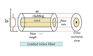
Figure: 24Graded Index Fibres: The refractive index of the optical fibre decreases as the radial distance from the fibre axis increases. GRIN fibre is one in which the refractive index varies radially, decreasing continuously in a parabolic manner from the maximum value of n1, at the center of the core to a constant value of n2 at the core-cladding interface.In graded-index fibre, light rays travel at different speeds in different parts of the fibre because the refractive index varies throughout the fibre. Near the outer edge, the refractive index is lower. As a result, rays near the outer edge travel faster than the rays at the center of the core. Because of this, rays arrive at the end of the fibre at approximately the same time. In effect light rays that arrive at the end of the fibre are continuously refocused as they travel down the fibre. All rays take the same amount of time in traversing the fibre. This leads to small pulse dispersion.
Figure: 25
For a parabolic index fibre, the pulse dispersion is reduced by a factor of about 200 in comparison to step-index fibre. It is because of this reason that first and second-generation optical communication systems used near parabolic index fibres.Q27) Question:Define Gauss’s law? What is the value of Gauss’s law in free space?A27) The law was published posthumously in 1867 as part of a collection of work by the famous German mathematician Carl Friedrich Gauss.Gauss’s law for the electric field describes the static electric field generated by a distribution of electric charges. It states that the electric flux through any closed surface is proportional to the total electric charge enclosed by this surface.let’s calculate the electric flux through a spherical surface around a positive point charge q, since we already know the electric field in such a situation. Recall that when we place the point charge at the origin of a coordinate system, the electric field at a point P that is at a distance rfrom the charge at the origin is given by
 is the radial vector from the charge at the origin to the point P. We can use this electric field to find the flux through the spherical surface of radius r, as shown in Figure 2.
Figure 1: A closed spherical surface surrounding a point charge q.Then we apply Φ=∫S  ⋅
⋅ dAto this system and substitute known values. On the sphere,
  and r=Rso for an infinitesimal area dA,
We now find the net flux by integrating this flux over the surface of the sphere
where the total surface area of the spherical surface is 4πR2. This gives the flux through the closed spherical surface at radius r asΦ=q/ϵ0A remarkable fact about this equation is that the flux is independent of the size of the spherical surface. This can be directly attributed to the fact that the electric field of a point charge decreases as 1/r2 with distance, which just cancels the r2 rate of increase of the surface area.Gauss' Law is the first of Maxwell's Equations which dictates how the Electric Field behaves around electric charges. Gauss' Law can be written in terms of the Electric Flux Density and the Electric Charge Density as: ∇·E = ρ/ε0 0r∇·D = ρ Hence, Gauss' law is a mathematical statement that the total Electric Flux exiting any volume is equal to the total charge inside. Hence, if the volume in question has no charge within it, the net flow of Electric Flux out of that region is zero. If there is positive charge within a volume, then there exists a positive amount of Electric Flux exiting any volume that surrounds the charge. If there is negative charge within a volume, then there exists a negative amount of Electric Flux exiting (i.e. the Electric Flux enters the volume).In integral form
in differential form∇·E = ρ/ε0 But in free space charge ρ is zero so ∇·E =0
|
|
|
|
|

 is the radial vector from the charge at the origin to the point P. We can use this electric field to find the flux through the spherical surface of radius r, as shown in Figure 2.
|
 ⋅
⋅ dAto this system and substitute known values. On the sphere,
  and r=Rso for an infinitesimal area dA,
|
|

in differential form∇·E = ρ/ε0 But in free space charge ρ is zero so ∇·E =0
0 matching results found


