Aryabhatta Knowledge University (AKU)
Civil Engineering
Surveying & Geomatics
Solved Exam Paper 2019
Q. Discuss different types of levelling with the help of suitable diagram(s).
Ans:
Types of Leveling in Surveying
- Direct leveling
- Trigonometric leveling
- Barometric leveling
- Stadia leveling
Direct Leveling
It is the most used method of leveling. In this method, measurements are observed directly from leveling instrument.
Based on the observation points and instrument positions direct leveling is divided into different types as follows:
- Simple leveling
- Differential leveling
- Fly leveling
- Profile leveling
- Precise leveling
- Reciprocal leveling
Simple Leveling
It is a simple and basic form of leveling in which the leveling instrument is placed between the points which elevation is to be find. Leveling rods are placed at that points and sighted them through leveling instrument. It is performed only when the points are nearer to each other without any obstacles.
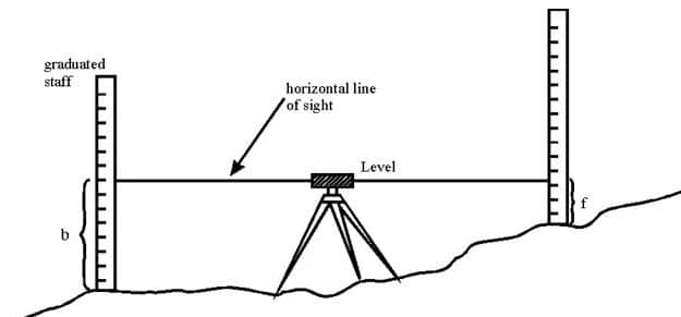
Differential Leveling
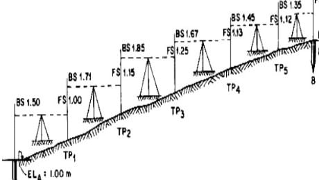
Differential leveling is performed when the distance between two points is more. In this process, number of inter stations are located and instrument is shifted to each station and observed the elevation of inter station points. Finally difference between original two points is determined.
Pregnancy test with raised bumps for blind parents

Fly Leveling
Fly leveling is conducted when the benchmark is very far from the workstation. In such case, a temporary benchmark is located at the workstation which is located based on the original benchmark. Even it is not highly precise it is used for determining approximate level.
Profile Leveling
Profile leveling is generally adopted to find elevation of points along a line such as for road, rails or rivers etc. In this case, readings of intermediate stations are taken, and reduced level of each station is found. From this cross section of the alignment is drawn.

Precise Leveling
Precise leveling is similar to differential leveling but, in this case, higher precise is wanted. To achieve high precise, serious observation procedure is performed. The accuracy of 1 mm per 1 km is achieved.
Reciprocal Leveling
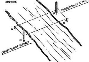
When it is not possible to locate the leveling instrument in between the inter visible points, reciprocal leveling is performed. This case appears in case of ponds or rivers etc. in case of reciprocal leveling, instrument is set nearer to 1st station and sighted towards 2nd station.
Trigonometric Leveling
The process of leveling in which the elevation of point or the difference between points is measured from the observed horizontal distances and vertical angles in the field is called trigonometric leveling.
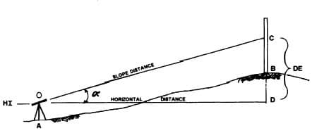
In this method, trigonometric relations are used to find the elevation of a point from angle and horizontal distance so, it is called as trigonometric leveling. It is also called as indirect leveling.
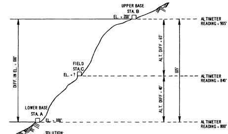
Barometric Leveling
Barometer is an instrument used to measure atmosphere at any altitude. So, in this method of leveling, atmospheric pressure at two different points is observed, based on which the vertical difference between two points is determined. It is a rough estimation and used rarely.
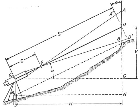
Stadia Leveling
It is a modified form of trigonometric leveling in which Tacheometer principle is used to determine the elevation of point. In this case the line of sight is inclined from the horizontal. It is more accurate and suitable for surveying in hilly terrains.
Q. What are different types of bearing?
Discuss the method of converting a whole circle bearing to reduced bearing.
Answer:
The horizontal angle between the reference meridian and the survey line is termed as bearing of the survey line.
Magnetic Bearing:
The magnetic needle of the compass always points towards the magnetic north-south (N-S) direction indicating earth’s magnetic axis. Since this direction is same at all the places on the earth’s surface, it is universally used as the reference direction. The angle made by survey line in a clockwise direction with reference to magnetic N-S line is termed as magnetic bearing of the line. The value of magnetic bearing ranges from 00 to 360o
True Bearing:
The geographical north of earth is different from the magnetic north. Hence, the angle which the survey line makes with the true geographical north is termed as true bearing of the survey line.
Arbitrary Bearing:
It is the horizontal angle which a survey line makes with any arbitrary meridian, which is any convenient direction towards a permanent and prominent mark or signal, such as a church spire or top of a chimney. Such bearings are used to determine the relative position of line in a small area.
Whole Circle Bearing (WCB):
The complete circle of angular measurement starts with north as 0o and ends at north at 360o. The bearing of line directly obtained by magnetic needle ranging from 0 o to 360 o is called whole circle bearing.
Reduced Bearing (RB):
The more convenient way to comprehend the direction of a survey line is to represent the bearing on a quadrantal system. The angle is measured with respect to N–S line towards east or west.
Fore Bearing (FB):
The angle measured in the direction of survey line from starting survey station to the next station is called fore bearing. If the bearing of line AB is measured from A towards B, it is known as forward bearing or fore bearing.
Back Bearing (BB):
It is the bearing of the survey line taken from the forward survey station to the preceding station from which the fore bearing was taken earlier. In Figure, if the bearing of same line AB is measured from B towards A, it is known as backward bearing or back bearing.
Converting a whole circle bearing to reduced bearing
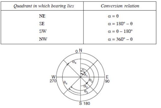
In whole circle bearing (WCB) the bearing of a line at any point is measured with respect to a meridian. Its value varies from zero to 360°, increasing in clockwise direction. Zero is north direction, 90° is east, 180° is south and 270° is west (Ref. Fig). This type of bearing is used in prismatic compass.
In reduced bearing (RB) system, bearings are measured from north or south direction towards east or west. Hence, angles are from 0° to 90° as shown in Fig. This system of measuring bearings is used in Surveyor’s compass and it is also known as Quadrantal Bearing (QB). The bearing measured is designated with letter N or S in the beginning to indicate whether it is from north or south. The letter E or W written after the angle indicates whether the bearing read is towards east or west, respectively.
The conversion of the bearing from one system to the other system can be easily carried out by drawing a sketch to indicate WCB or RB as shown in Fig. It may be observed that conversion table is as given below:
Q. Discuss the different instruments used in plane table surveying. Also explain the method of intersection in plane table surveying.
Answer:
The following instruments are required to carry out plane table survey:
- Alidade
- Plumbing fork with plumb bob
- Spirit level
- Trough compass
- Drawing sheets and accessories for drawing.
1. Alidade
It is a straight edge ruler having some form of sighting device. One edge of the ruler is beveled and is graduated. Always this edge is used for drawing line of sight. Depending on the type of line of sight there are two types of alidade:
Pregnancy test with raised bumps for blind parents
(a) Plain alidade
(b) Telescopic alidade
Plain Alidade:
Figure shows a typical plain alidade. A sight vane is provided at each end of the ruler. The vane with narrow slit serves as eye vane and the other with wide slit and having a thin wire at its center serves as object vane.
The two vanes are provided with hinges at the ends of ruler so that when not in use they can be folded on the ruler. Plain alidade is not suitable in surveying hilly areas as the inclination of line of sight in this case is limited.
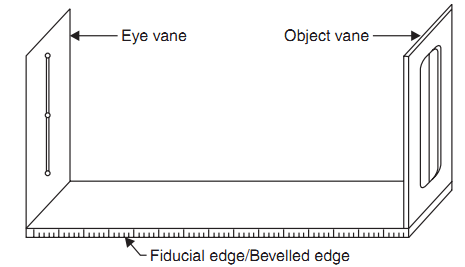
Fig: – Plane Alidade
Telescopic Alidade:
It consists of a telescope mounted on a column fixed to the ruler [Fig.]. The line of sight through the telescope is kept parallel to the beveled edge of the ruler. The telescope is provided with a level tube and vertical graduation arc. If horizontal sight is required bubble in the level tube is kept at the center. If inclined sights are required vertical graduation helps in noting the inclination of the line of sight. By providing telescope the range and the accuracy of line of sight is increased.
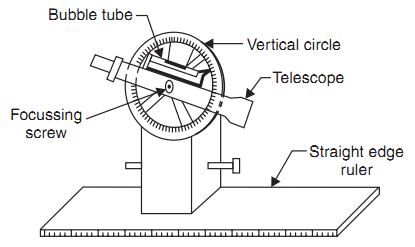
Telescopic alidade
2. Plumbing Fork and Plumb Bob
Figure shows a typical plumbing fork with a plum bob. Plumbing fork is a U-shaped metal frame with a upper horizontal arm and a lower inclined arm. The upper arm is provided with a pointer at the end while the lower arm is provided with a hook to suspend plumb bob.
When the plumbing fork is kept on the plane table the vertical line (line of plumb bob) passes through the pointed edge of upper arm. The plumb bob helps in transferring the ground point to the drawing sheet and vice versa also.
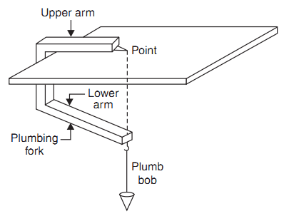
Fig.: Plumbing fork and plumb bob
3. Spirit Level
A flat based spirit level is used to level the plane table during surveying (Fig.5). To get perfect level, spirit level should show central position for bubble tube when checked with its positions in any two mutually perpendicular directions.
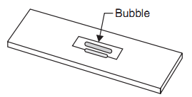
Fig.: Spirit level
4. Trough Compass
It consists of a 80 to 150 mm long and 30 mm wide box carrying a freely suspended needle at its center (Ref. Fig.). At the ends of the needle graduations are marked on the box to indicate zero to five degrees on either side of the center. The box is provided with glass top to prevent oscillation of the needle by wind.
When needle is centered (reading 0–0), the line of needle is parallel to the edge of the box. Hence marking on the edges in this state indicates magnetic north–south direction.
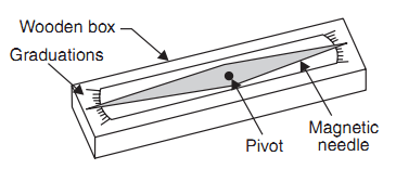
Fig: Trough compass
5. Drawing Sheet and Accessories for Drawing
A good quality, seasoned drawing sheet should be used for plane table surveying. The drawing sheet may be rolled when not in use but should never is folded. For important works fibre glass sheets or paper backed with thin aluminum sheets are used. Clips clamps, adhesive tapes may be used for fixing drawing sheet to the plane table. Sharp hard pencil, good quality eraser, pencil cutter and sandpaper to keep pencil point sharp are other accessories required for the drawing work. If necessary, plastic sheet should be carried to cover the drawing sheet from rain and dust.
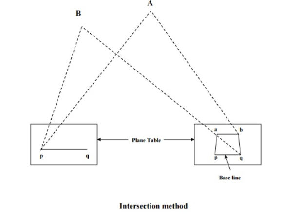
Method of intersection in plane table surveying
This method is useful where it is not possible to measure the distances on ground as in case of a mountainous country. Hence, this method is employed for locating inaccessible points, the broken boundaries, rivers, fixing survey stations, etc. The procedure is as follows:
- Select two stations P and Q so that the points to be located on paper are easily seen from them.
- Plot the line pq, which is known as the base line, on paper. This can be done in one of the two ways:
a) The table can be centered and leveled at station P and then after orienting at station Q, the distance PQ can be accurately measured and put up to some scale on the paper.
b) The line pq can be drawn to some scale on the paper and then the board can be adjusted from station P by back sighting at station Q.
Iii. From station P, draw rays for stations A, B, etc.
Iv. Shift the table to station Q and after proper orientation, take rays of stations A, B etc.,
v. The intersection of rays from stations P and Q will give points a, b etc. on paper, as shown in figure.
For checking the accuracy of work, measure the distance AB on ground and compare it with its corresponding length ab on paper.
Q. Explain the temporary adjustments for angle measurement using Vernier theodolite
Answer:
Theodolite has two types of adjustments-temporary and permanent. Temporary adjustments are to be done at every station the instrument is set up. Permanent adjustments deal with the fundamental lines and their relationships and should be done occasionally to ensure that the instrument is properly adjusted.
The temporary adjustments are the following:
1) setting up and centering,
2) levelling,
3) focusing the eyepiece, and
4) focusing the objective.
- Setting Up and Centring
The following procedure is adopted for this operation.
1. Remove the theodolite from its box carefully and fix it onto a tripod kept over the station where the instrument is to be set up. The tripod legs should be well apart, and the telescope should be at a convenient height for sighting.
2. Tie a plumb bob onto the hook provided at the base. If there is no shifting head in the instrument, Centre it by adjusting the tripod legs and shifting the instrument to bring the plumb bob over the station mark.
3. To Centre the plumb bob, shift the tripod legs radially as well as circumferentially. Moving any leg radially shifts the plumb bob in the direction of the leg. This does not affect the level status of the instrument. Moving any leg circumferentially does not appreciably shift the plumb. However, this movement tilts the instrument and affects the level of the plate bubbles. By moving the legs the plumb bob is brought over the station mark at the same time ensuring that the instrument is approximately level. This saves a lot of time for the next operation of levelling.
4. If the instrument has a shifting head with a clamp, first Centre the instrument using legs. Make the final adjustment by loosening the clamp and shifting the head (or the instrument as a whole) to bring the plumb bob over the station mark. In all operations, the starting step should be to first bring the plumb bob very close to the mark and then make the final adjustment using the legs or the shifting head.
2. Levelling
After setting up and centring the instrument, levelling is done. Levelling must be done at every station the instrument is set up. By levelling the instrument, it is ensured that as the instrument is swung about the vertical axis, the horizontal plate moves in a horizontal plane. The instrument may have a three-screw or a four-screw levelling head. The levelling operations differ slightly in these two cases as detailed in the following sections. Most instruments have only one bubble tube, but some instruments have two bubble tubes set at right angles over the plates.
Three-screw levelling head
1. Swing the theodolite and bring the plate bubble parallel to any two of the foot screws. Centre the bubble by rotating the foot screws. To do this, hold the foot screws by the unbind rehinge each hand and rotate both either inwards or outwards [see Fig. (a)]. Also note that the bubble moves in the direction of movement of the left thumb during this operation.
2. Once the bubble traverses (or comes to the central position from the graduation of the tube), swing the instrument and bring the bubble over the third foot screw. In this position, the bubble tube is at right angles to the earlier position. Centre the bubble by rotating the third foot screw alone.
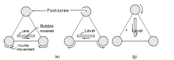
Fig. Three-foot-screw levelling head
3. Bring the plate bubble to its previous position by swinging the instrument back. Check whether the bubble traverses. If it does not traverse, bring the bubble to the Centre using the two-foot screws as before.
4. Repeat the procedure till the bubble traverses in both these positions.
5. Swing the instrument through 1800 and check whether the bubble traverses. The bubble should traverse in all positions if the instrument has been properly adjusted.
If two plate bubbles are provided [see Fig. (b)], the procedure is the same except that swinging the instrument through 900 is not required. When one plate level is kept parallel to a pair of foot screws, the other plate level is over the third foot screw (in a perpendicular direction). The third foot screw is adjusted alternately by the same process using the foot screws over which they are parallel.
Four-screw levelling head
When the theodolite has a four-screw levelling head, the following procedure is adopted.
1. After setting up and centering the theodolite, bring the plate level parallel to any one pair of diagonally opposite foot screws. Operate these foot screws to Centre the bubble (Fig.).
2. Swing the instrument to bring the plate level parallel to the other pair of foot screws. Centre the bubble.
3. Swing it back to the previous position. Check whether the bubble traverses. If it does not, Centre it with the foot screws to which the level is parallel.
4. Swing it back, check the position of the bubble, and repeat the procedure.
5. Once the bubble traverses in the two orthogonal positions, swing it through 1800. The bubble should traverse in this position or in any other position.
If two plate levels are provided, the procedure is the same. Bring one plate level parallel to a pair of opposite foot screws. The other pair will be parallel to the remaining pair of foot screws. There is no need to swing the instrument. Bring the bubble to the central position alternately and check in the other positions.

Fig. Four-foot-screw levelling head
3. Focusing the Eyepiece
Focusing the eyepiece is the operation of bringing the cross hairs to focus. The focusing position varies with the eyesight of the observer. If the same observer is taking the readings, this has to be done only once. To focus the eyepiece, use the following procedure.
1. Keep a piece of white paper in front of the telescope or direct the telescope towards a clear portion of the sky.
2. Looking through the telescope, adjust the vision by rotating the eyepiece till the cross hairs come into sharp and clear view.
3. If the eyepiece has graduations, note the graduation at which you get a clear view of the cross hairs. This can help in later adjustment if required.
Q. What do you mean by baseline in triangulation? Explain in detail a method to set out the baseline.
Answer:
Triangulation is a surveying method that measures the angles in a triangle formed by three survey control points. Using trigonometry and the measured length of just one side, the other distances in the triangle are calculated. The shape of the triangles is important as there is a lot of inaccuracy in a long skinny triangle, but one with base angles of about 45 degrees is ideal.
Each of the calculated distances is then used as one side in another triangle to calculate the distances to another point, which in turn can start another triangle. This is done as often as necessary to form a chain of triangles connecting the origin point to the Survey Control in the place needed. The angles and distances are then used with the initial known position, and complex formulae, to calculate the position (Latitude and Longitude) of all other points in the triangulation network. Although the calculations used are like the trigonometry taught in high school, because the distance between the survey points is generally long (typically about 30 kilometers) the calculations also allow for the curvature of the Earth.
The measured distance in the first triangle is known as the ‘Baseline’ and is the only distance measured; all the rest are calculated from it and the measured angles. The distance can be relatively short (maybe a kilometer or so) and it would be in a reasonably flat area, such as a valley or plain. The triangles measured from it gradually increased in size, and up onto the hilltops where distant points could be seen easily.
The angles in the triangles are measured using a theodolite, which is an instrument with a telescope connected to two rotating circles (one horizontal and one vertical) to measure the horizontal and vertical angles. A good quality theodolite used for geodetic surveys would be graduated to 0.1 second of an arc and an angle resulting from repeated measurements would typically have an accuracy of about 1 second of arc, which is equivalent to about 5 cm over 10 kilometers. The measurement of baseline has an important role in the triangulation surveying, because the accuracy of computation of sides of the triangle depends upon the accuracy of the measured base line.
Before measure of baseline a site will be chosen based on following conditions.
- The site should be fairly level or uniformly sloping or gently undulating.
- It should be free from obstructions throughout the whole of its length.
- The extremities of the baseline being visible at ground level.
- The ground should be firm and smooth.
- The selection of sites taken in the mind if the triangle is formed well shaped triangles.
The equipment required to measure the baseline.
- Three standardized tapes
- Straining device.
- Weight and pulley
- Finally, divided pocket scale
- Supporting tripods or stakes,
- Steel tape for setting out tripod’s stakes
- Thermometers
Procedure: - Before starting the measurement make sure that the align of the line is free from all types of obstruction and leveled.
The line is divided into sections and aligned by transit instrument. A series of such posts (marking or measuring posts) are accurately driven on the line with their tops about 0.6m above the ground surface at intervals slightly less than one tape length. Supporting stakes are driven 15 to 30 meters intervals.
If very accurate work use tripods instead of posts. To measure the baseline. The tape is stretched between the marking posts or tripods and hangs freely. The rear ends of the tape are connected to the straining posts and forward end of spring balance. In the case of tripods two tripods required for measuring baseline one is a straining tripod and another is measuring tripods. The proper tensions then applied at the forward posts and measured the temperature with the help of thermometers. Reading of each end of tape, the exact distance between the marks on tripod heads is determined, the reading on the scale corresponding to the mark being read with a microscope.
Correction applied in measurement of base line
- Correction for absolute length
- Correction for temperature
- Correction for tension or pull
- Correction for sag
- Correction for slope
- Reduction to sea level
The tape is then carried forward and the process repeated until the end of the section is reached. The section is again measured in the reverse direction as a check. If the two measurement agree within the permissible limit, The measurement of a long baseline may sometimes be difficult due to obstacles or the level
ground being of limited extent, only portion of the baseline accurately measured which is then prolonged by ranging lines in continuation of it, at one or both ends, suitable lengths obtained to give well- conditioned angles from its end to the points to be fixed. The lengths of the additional Lines are calculated from the measured base and the observed angles.
Q. Discuss the basic components of a total station. Discuss in detail about the different applications of total station for civil engineering projects.
Answer:
Total Station is an equipment used in surveying, designed for measuring horizontal and vertical angles, inclusive of measuring sloping distance of object to the instrument. It is a combination of electronic theodolite and electromagnetic distance measuring (EDM) instrument. It also consists of a micro-processor with a memory unit which deals with recordings, readings, and the fundamental calculation of measurements.
Components of a Total Station
Total Station is a compact instrument which weighs around 50 N to 55 N. It consists of a distance measuring instrument (EDM), an angle measuring instrument (Theodolite) and a simple microprocessor. The components used in Total station surveying are:
- A tripod is used to hold the total station
- An electronic notebook used to record, calculate and even manipulate the field data
- Prism and prism pole which can measure lengths up to 2 km and up to 6-7 km can be measured with triple prism
- Battery
Functions Performed by Total Stations
Total Stations, with their microprocessors, can perform a variety of functions and computations, depending on how they are programmed. The capabilities vary with different instruments, but some standard computations include:
- Averaging multiple angle and distance measurements.
- Correcting electronically measured distances from prism constant, atmospheric pressure, and temperature.
- Making curvature and refraction corrections to elevations determine by trigonometric levelling.
- Reducing slope distances to their horizontal and vertical components.
- Calculating point elevations from the vertical distance components (supplemented with keyboard input of instrument and reflector heights).
- Computing coordinates of survey points from horizontal angle and horizontal distance.
- Averages multiple angle measurements.
- Averages multiple distance measurements.
- Computes horizontal and vertical distances.
- Corrections for temp, pressure and humidity.
- Computes inverses, polars, resections.
- Computes X, Y and Z coordinates.
Applications of Total Station
There are many other facilities available, the total station can be used for the following purposes.
- Detail survey i.e., data collection.
- Control Survey (Traverse).
- Height measurement (Remove elevation measurement- REM).
- Fixing of missing pillars (or) Setting out (or) Stake out.
- Resection.
- Area calculations, etc.
- Remote distance measurement (RDM) or Missing line measurement (MLM).
- Data Collection
Measurements can be stored “on board” with all the total stations. The two options that are available are
- Data can be stored directly in the memory of the microcomputer, and later downloaded to an external storage device via a RS – 232 connections.
- The second option is the removable memory card. When one card is full, it can be removed, and another card can be quickly installed.
2. Detail Survey
Given two points whose coordinates are known, a total station can be used to get the coordinates of various other points based upon those two co-ordinates. Care should be taken that the new points survey are carefully coded. The Map of the area can be obtained after downloading and processing.
3. Control Survey / Traverse:
It is like any type of EDM Traverse.
Traverse is the method of control survey in providing horizontal and vertical controls along a pre-defined route by means of establishing a series of connected lines joining the traverse stations.
- In traverse several connected survey lines form a framework of survey.
- The direction and length of survey lines are measured with the help of an angular measuring device (Theodolite) and distance measuring device (Tape, chain, EDM, GPS etc.).
4. Remote Elevation Measurement (REM)
The process of finding the height of objects without actually going to the top of the object is known as Remote Elevation Measuring (REM) i.e., a total station placed remotely (faraway) from the object is used to measure the heights.
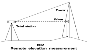
Method: The prism is kept at the base of the object sight the telescope to the prism, and measure the slope distance ‘d’, now tilt the telescope up-to the tip of the object. The height of the object is displayed, from the bottom of the prism depending upon the instrument.
This feature measures the elevation of a point where a prism cannot be placed directly. The measurement is extended along the plumb line while the elevation is continuously displayed.
Remote Elevation Measurement:
Advantages of total station
- In area computation, it achieves high accuracy because of the possibility of taking arcs.
- Quick visualization does with the help of a graphical view of land and plots.
- With the help of laser plummets, it required less time to set on the tripod.
- When the field works are completed, the area map with dimensions is ready after the data transfer.
- There is a requirement of any scale at any user because of enormous plotting and area computation.
- It supports the local language.
- It provides automation of old maps.
- Full GIS creation.
- It provides integration of databases.
Q. Draw a neat diagram of a simple circular curve. With the help of the diagram, explain the various elements of a simple circular curve.
Answer:
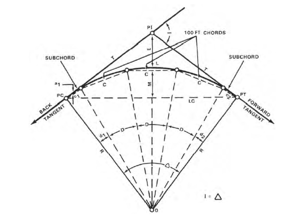
Fig: simple circular curve
Point of Intersection (PI)
The point of intersection marks the point where the back and forward tangents intersect. The surveyor indicates it as one of the stations on the preliminary traverse.
Intersecting Angle (I)
The intersecting angle is the deflection angle at the PI. The surveyor either computes its value from the preliminary traverse station angles or measures it in the field.
Radius (R)
The radius is the radius of the circle of which the curve is an arc.
Point of Curvature (PC)
The point of curvature is the point where the circular curve begins. The back tangent is tangent to the curve at this point.
Point of Tangency (PT)
The point of tangency is the end of the curve. The forward tangent is tangent to the curve at this point.
Length of Curve (L)
The length of curve is the distance from the PC to the PT measured along the curve.
Tangent Distance (T)
The tangent distance is the distance along the tangents from the PI to the PC or PT. These distances are equal on a simple curve.
Central Angle (Δ)
The central angle is the angle formed by two radii drawn from the center of the circle (0) to the PC and PT. The central angle is equal in value to the I angle.
Long Chord (LC)
The long chord is the chord from the PC to the PT.
External Distance (E)
The external distance is the distance from the PI to the midpoint of the curve. The external distance bisects the interior angle at the PI.
Middle Ordinate (M)
The middle ordinate is the distance from the midpoint of the curve to the midpoint of the long chord. The extension of the middle ordinate bisects the central angle.
Degree of Curve (D)
The degree of curve defines the “sharpness” or “flatness” of the curve (figure). There are two definitions commonly in use for degree of curve, the arc definition and the chord definition.
Arc definition:
The arc definition states that the degree of curve (D) is the angle formed by two radii drawn from the center of the circle (point O) to the ends of an arc 100 feet or 30.48 meters long. In this definition, the degree of curve and radius are inversely proportional using the following formula:

As the degree of curve increases, the radius decreases. It should be noted that for a given intersecting angle or central angle, when using the arc definition, all the elements of the curve are inversely proportioned to the degree of curve. This definition is primarily used by civilian engineers in highway construction.
Chord definition
The chord definition states that the degree of curve is the angle formed by two radii drawn from the center of the circle (point O, figure 3) to the ends of a chord 100 feet or 30.48 meters long. The radius is computed by the following formula:

The radius and the degree of curve are not inversely proportional even though, as in the arc definition, the larger the degree of curve the “sharper” the curve and the shorter the radius. The chord definition is used primarily on railroads in civilian practice and for both roads and railroads by the military.
Deflection Angles
The deflection angles are the angles between a tangent and the ends of the chords from the PC. The surveyor uses them to locate the direction in which the chords are to be laid out. The total of the deflection angles is always equal to one half of the I angle. This total serves as a check on the computed deflection angles.
Chords
On curves with long radii, it is impractical to stake the curve by locating the center of the circle and swinging the arc with a tape. The surveyor lays these curves out by staking the ends of a series of chords (figure). Since the ends of the chords lie on the circumference of the curve, the surveyor defines the arc in the field. The length of the chords varies with the degree of curve.
Q. What do you understand by GPS? How is it helpful in mapping of a region?
Answer:
GPS, which stands for Global Positioning System, is the only system today able to show you your exact position on the Earth anytime, in any weather, anywhere. Ground stations, located worldwide, continuously monitor them. The satellites transmit signals that can be detected by anyone with a GPS receiver. Using the receiver, you can determine your location with great precision. GPS is one of history’s most exciting and revolutionary developments, and new uses for it are constantly being discovered.
GPS Elements
GPS has 3 parts: the space segment, the user segment, and the control segment. The space segment consists of 24 satellites, each in its own orbit 11,000 nautical miles above the Earth. The user segment consists of receivers, which you can hold in your hand or mount in your car. The control segment consists of ground stations (five of them, located around the world) that make sure the satellites are working properly. The GPS satellites each take 12 hours to orbit the Earth. Satellites are equipped with very precise clocks that keep accurate time to within three nanoseconds – that’s 0.000000003, or three billionths, of a second. This precision timing is important because the receiver must determine exactly how long it takes for signals to travel from each GPS satellite. To help you understand the GPS system, let’s take the three parts of the system – the satellites, the receivers, and the ground control – and discuss them in more detail.
Satellites in Space
The first GPS satellite was launched in 1978. The first 10 satellites were developmental satellites, called Block I. From 1989 to 1993, 23 production satellites, called Block II, were launched. The launch of the 24th satellite in 1994 completed the system.
Ground Control Stations and Receivers
The GPS control, or ground, segment consists of unmanned monitor stations located around the world (Hawaii and Kwajalein in the Pacific Ocean; Diego Garcia in the Indian Ocean; Ascension Island in the Atlantic Ocean; and Colorado Springs, Colorado); a master ground station at Schriever (Falcon) Air Force Base in Colorado Springs, Colorado; and four large ground antenna stations that broadcast signals to the satellites. The stations also track and monitor the GPS satellites.
Receivers
GPS receivers can be hand carried or installed on aircraft, ships, tanks, submarines, cars, and trucks. These receivers detect, decode, and process GPS satellite signals. The typical hand-held receiver is about the size of a cellular telephone, and the newer models are even smaller weighed only 28 ounces.
How GPS Works
So you can more easily understand some of the scientific principles that make GPS work, let’s discuss the basic features of the system. The principle behind GPS is the measurement of distance (or “range”) between the receiver and the satellites. The satellites also tell us exactly where they are in their orbits above the Earth. It works something like this: If we know our exact distance from a satellite in space, we know we are somewhere on the surface of an imaginary sphere with radius equal to the distance to the satellite radius. If we know our exact distance from two satellites, we know that we are located somewhere on the line where the two spheres intersect. And, if we take a third measurement, there are only two possible points where we could be located. One of these is usually impossible, and the GPS receivers have mathematical methods of eliminating the impossible location.
Mapping of a region using GPS
When used by skilled professionals, GPS provides surveying and mapping data of the highest accuracy. GPS-based data collection is much faster than conventional surveying and mapping techniques, reducing the amount of equipment and labor required. A single surveyor can now accomplish in one day what once took an entire team weeks to do.
GPS supports the accurate mapping and modeling of the physical world — from mountains and rivers to streets and buildings to utility lines and other resources. Features measured with GPS can be displayed on maps and in geographic information systems (GIS) that store, manipulate, and display geographically referenced data.
Governments, scientific organizations, and commercial operations throughout the world use GPS and GIS technology to facilitate timely decisions and wise use of resources. Any organization or agency that requires accurate location information about its assets can benefit from the efficiency and productivity provided by GPS positioning.
Unlike conventional techniques, GPS surveying is not bound by constraints such as line-of-sight visibility between survey stations. The stations can be deployed at greater distances from each other and can operate anywhere with a good view of the sky, rather than being confined to remote hilltops as previously required.
GPS is especially useful in surveying coasts and waterways, where there are few land-based references. Survey vessels combine GPS positions with sonar depth soundings to make the nautical charts that alert mariners to changing water depths and underwater hazards. Bridge builders and offshore oil rigs also depend on GPS for accurate hydrographic surveys.
Land surveyors and mappers can carry GPS systems in backpacks or mount them on vehicles to allow rapid, accurate data collection. Some of these systems communicate wirelessly with reference receivers to deliver continuous, real-time, centimeter-level accuracy and unprecedented productivity gains.
Q. What are the different methods for GPS surveying? Explain any one of them in detail.
Answer:
Different methods for GPS surveying
- Static and Kinematic GPS surveying techniques: High precision techniques based on post processing of carrier phase measurements
- Differential GPS (DGPS): instantaneous low to moderate accuracy positioning and mapping technique based on pseudo range measurements.
- Real – Time Kinematic (RTK): versatile high precision techniques that use carrier phase measurements in an instantaneous positioning mode
- Stop-and-Go GPS Surveying
Rapid static GPS surveying:
This is also referred to as fast-static or quick-static. The following characteristics distinguish rapid-static techniques from other methods of static GPS surveying:
- Observational time requirements: these are significantly shorter than the conventional static GPS surveying, and are a function of baseline length, whether dual frequency instruments are used, number of satellites being tracked and satellite geometry. Typically the receivers need only occupy a baseline for a period of 10-30 minutes (the lower value corresponding to baseline <5 Km and tracking six or more satellite, the upper value being for longer baseline up to 20 Km and / or tracking is to only four satellites).
- Hardware requirements: in most systems only dual-frequency phase measurements are enough; while in other configurations dual frequency pseudo range measurements are also required. It is rare to mix different brands of receivers and software, compared to static GPS surveying techniques.
- Specialized software: the basis of this technique is the ability of the soft ware to resolve the ambiguities using a very short observation period. There is a variety of software, with different characteristics and levels of sophistication’s, but the fundamental requirement is a fast ambiguity resolution (AR) capability. Dual frequency data is essential for fast AR.
The field procedures are much like those for conventional static GPS surveying except:
(a) the station occupation times are shorter
(b) baseline should be comparatively short
(c) the satellite geometry favorable
(d) signal disturbances such as multi path should be minimum. It is not possible to define exactly how much data needs to be collected in order to produce quality baselines every time, that is ambiguity fixed solutions. Equipment user manuals typically give guidelines in this regard.
The rapid-static technique is well suited, for short range applications such as control densification and engineering surveys or any job where many points need to be surveyed. Unlike kinematic and stop-and-go techniques there is no need to maintain lock on satellites when moving from one point to another.
Q. Describe various applications of remote sensing in the field of civil engineering with suitable examples.
Answer:
There are various applications of remote sensing which may be grouped into the following:
- Resource Exploration
- Environmental Study
- Land use
- Site Investigation
- Archaeological Investigation and
- Natural Hazards Study
Resource Exploration: Geologists use remote sensing to study the formation of sedimentary rocks and identify deposits of various minerals, detect oil fields and identify underground storage of water. Remote sensing is used for identifying potential fishing zone, coral reef mapping and to find other wealth from ocean.
Environmental Study: Remote sensing is used to study cloud motion and predict rains. With satellite data it is possible to study water discharge from various industries to find out dispersion and harmful effects, if any, on living animals. Oil spillage and oil slicks can be studied using remote sensing.
Land Use: By remote sensing, mapping of larger areas is possible in short time. Forest area, agricultural area, residential and industrial area can be measured regularly and monitored. It is possible to find out areas of different crops.
Site Investigation: Remote sensing is used extensively in site investigations for dams, bridges, pipelines. It can be used to locate construction materials like sand and gravel for the new projects.
Archaeological Investigation: Many structures of old era are now buried under the ground and are not known. But by studying changes in moisture content and other characteristics of the buried objects and upper new layer, remote sensors can recognize the buried structures of archaeological importance.
Natural Hazard Study: Using remote sensing the following natural hazards can be predicted to some extent and hazards minimized:
- Earthquake
- Volcanoes
- Landslides
- Floods and
- Hurricane and Cyclones