|
|
|
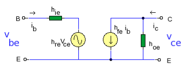
H-parameters are not constant and vary with temperature, collector current and collector emitter voltage. For this reason when designing a circuit the hybrid parameters should be measured under the same conditions as the actual circuit.The small signal parameter hreVce is often too small to be considered so the input resistance is just hie. Often the output resistance hoe is often large compared wi the the collector resistor RC and its effects can be ignored. The h-parameter equivalent model is now simplified and drawn below:
|
Input Impedance Zi
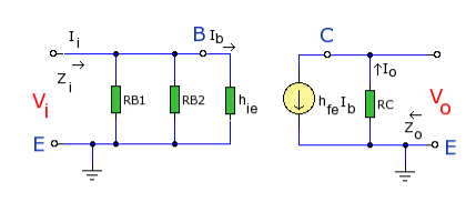
The input impedance is the parallel combination of bias resistors RB1 and RB2. As the power supply is considered short circuit at small signal levels then RB1 and RB2 are in parallel. RBB will represent the parallel combination:
As RBB is in parallel with hie then: Zi = RBB || hie Output Impedance Zo As hfeIb is an ideal current generator with infinite output impedance, then output impedance looking into the circuit is: Zo = RC Voltage Gain Av Note the − sign in the equation, this indicates phase inversion of the output waveform. as Ib = Vi / hie then:
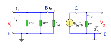
Current Gain AiThe current gain is the ratio Io / Ii. At the input the current is split between the parallel branch RBB and hie. So looking at the equivalent h-parameter model again (shown below):
|
|
The current divider rule can be used for Ib:
At the output side, Io = hfe Ib re-arranging Io / Ib = hfe
If RBB >> hie then,
|
● Can increase or decrease input impedance (depending on type of feedback).
● Can increase or decrease output impedance (depending on type of feedback).
● Reduces total distortion if sufficiently applied (increases linearity).
● Increases the bandwidth.
● Desensitizes gain to component variations.
● Can control step response of amplifier.
Cons:● May lead to instability if not designed carefully.
● Amplifier gain decreases.
● Input and output impedances of a negative-feedback amplifier (closed-loop amplifier) become sensitive to the gain of an amplifier without feedback (open-loop amplifier)—that exposes these impedances to variations in the open-loop gain, for example, due to parameter variations or nonlinearity of the open-loop gain.
● Changes the composition of the distortion (increasing audibility) if insufficiently applied.
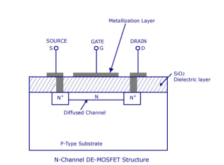
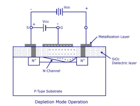
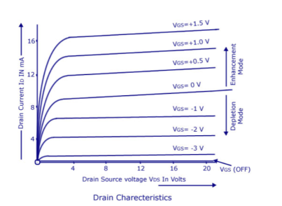
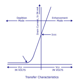
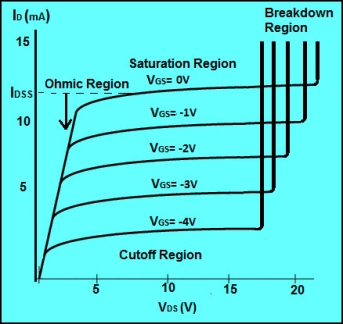
The most widely preferred amplifier among the two types of the amplifier is the negative feedback amplifier. The characteristics of this amplifier are:● In the topology of the feedback amplifiers in the voltage series feedback the input impedance value increases and the output impedance decreases.● In the topology of the voltage shunt feedback, both the input and the output resistances values are decreases.● In the current series feedback circuits, both the input and the output resistances are increased because of its topology.● In the current shunt feedback topology, the amplifiers input resistance decreases and the output resistance decreases because of its connectivity of the input, output and feedback circuit.● In this way, the characteristics are defined based on the various topologies. Each topology defined has its significance of utilization.Simple amplifiers like the common emitter configuration have primarily low-order distortion, such as the 2nd and 3rd harmonics. In audio systems, these can be minimally audible because musical signals are typically already a harmonic series, and the low-order distortion products are hidden by the masking effect of the human hearing system.After applying moderate amounts of negative feedback (10–15 dB), the low-order harmonics are reduced, but higher-order harmonics are introduced. Since these are not masked as well, the distortion becomes audibly worse, even though the overall THD may go down. This has led to a persistent myth that negative feedback is detrimental in audio amplifiers, leading audiophile manufacturers to market their amplifiers as "zero feedback" (even when they use local feedback to linearize each stage).However, as the amount of negative feedback is increased further, all harmonics are reduced, returning the distortion to inaudibility, and then improving it beyond the original zero-feedback stage (provided the system is strictly stable).So the problem is not negative feedback, but insufficient amounts of it. Question. With a neat diagram, explain the construction and operation of depletion MOSFET. Also write the drain and transfer characteristics.Answer: The basic construction of n-channel depletion type MOSFET is provided in the figure shown above. A slab of p-type material is formed from a silicon base and is referred to as the substrate.
|
|
|
|
|
|
|
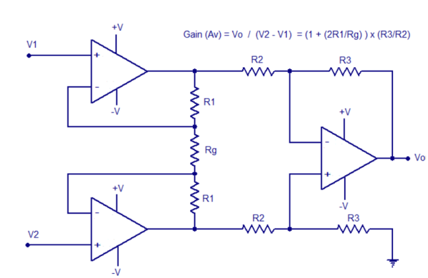
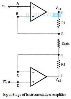
● The overall voltage gain of an instrumentation amplifier can be controlled by adjusting the value of resistor Rgain.
● The common mode signal attenuation for the instrumentation amplifier is provided by the difference amplifier.
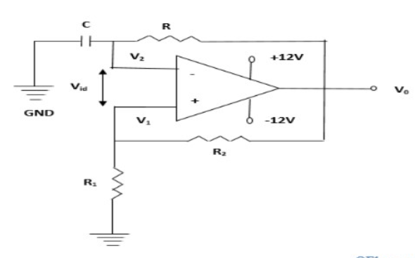
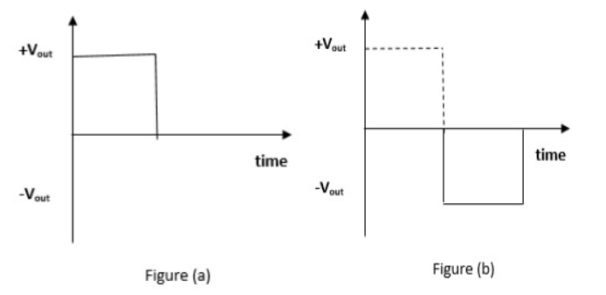
Question. With a neat circuit diagram, generate square wave form. Answer: To design the square wave generator, we need a capacitor, resistor, operational amplifier, and power supply. The capacitor and resistor are connected to the inverting terminal of the operational amplifier and the resistors R1 and R2 are connected to the non-inverting terminal of the operational amplifier. The circuit diagram of the square wave generator using an operational amplifier is shown below
|
|
|
|
|
|
|
|
|
|
