|
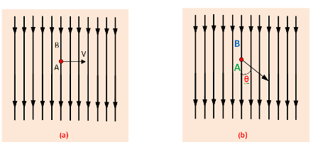
 If the conductor (A) moves at an angle θ with the direction of flux which is shown in (b).
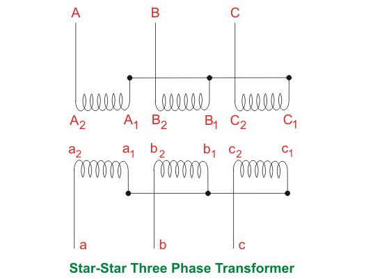
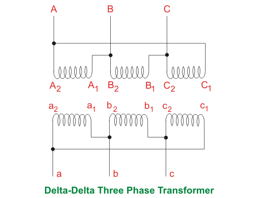
 An example, the generator works on the production of dynamically induced e.m.f in the conductors.Question. Differentiate between the following with one application of each with connection diagram and mathematical relationships:i) Three 1-phase transformers connected to form a 3-phase transformer bank of same ratings ii) One 3-phase transformerIt is found that generation, transmission, and distribution of electrical power are more economical in three phase system than a single phase system. For a three-phase system, three single-phase transformers are required. Three phase transformation can be done in two ways, by using a single three-phase transformer or by using a bank of three single phase transformers. There are advantages and disadvantages to each option.A single 3 phase transformer costs around 15 % less than a bank of three single phase transformers. Again former occupies less space than later. For a very big transformer, it is impossible to transport a large three-phase transformer to the site and is instead easier to transport three single-phase transformers, which are erected separately to form a three-phase unit.Another advantage of using a bank of three single phase transformers is that, if one unit of the bank becomes out of order, then the bank can be run as an open delta transformer.Connection of Three Phase TransformerA verity of connection of three phase transformer are possible on each side of both a single 3 phase transformer or a bank of three single phase transformers.Marking or Labeling the Different Terminals of TransformerTerminals of each phase of HV side should be labeled as capital letters, A, B, C and those of LV side should be labeled as small letters a, b, c. Terminal polarities are indicated by suffixes 1 and 2. Suffix 1’s indicate similar polarity ends and so do 2’s.Star-Star Transformer
|
|
|
|
Star-Star Transformer
Voltage difference between HV & LV winding,
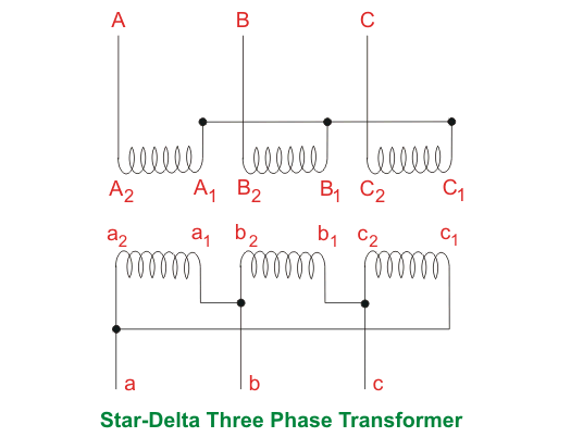
In Star-Delta Transformer
Voltage difference between HV & LV winding,
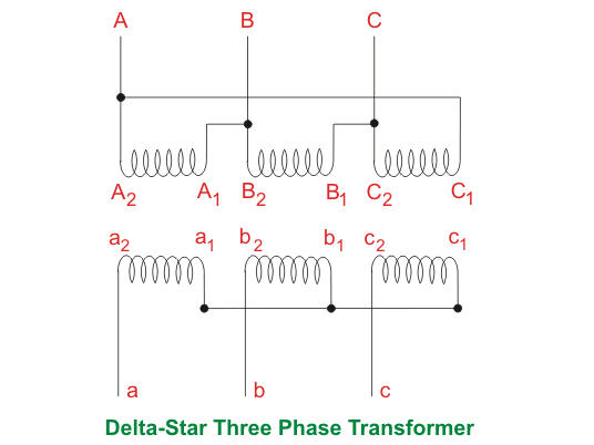
In Delta-Star Transformer
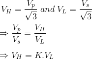
Voltage difference between HV & LV winding,
For 132/33KV Transformer K = 4 Case 1 Voltage difference between HV & LV winding,
Case 2 Voltage difference between HV & LV winding,
Case 3 Voltage difference between HV & LV winding,
|
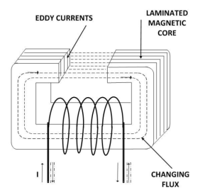
 ● The output power is the product of the fraction of the rated loading (volt-ampere), and power factor of the load● The losses are the sum of copper losses in the windings + the iron loss + dielectric loss + stray load loss.● The iron losses include the hysteresis and eddy current losses in the transformer. These losses depend on the flux density inside the core. Mathematically,
Hysteresis Loss :

Eddy Current Loss :

Where kh and ke are constants, Bmax is the peak magnetic field density, f is the source frequency, and t is the thickness of the core. The power ‘n’ in the hysteresis loss is known as Steinmetz constant whose value can be nearly 2.
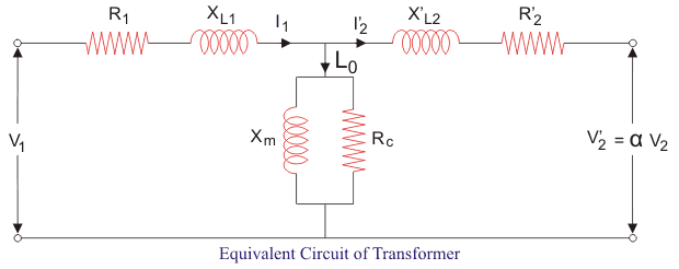
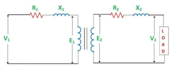
 ● The dielectric losses take place inside the transformer oil. For low voltage transformers, it can be neglected.● The leakage flux links to the metal frame, tank,etc. to produce eddy currents and are present all around the transformer hence called stray loss, and it depends on the load current and so named as ‘stray load loss.’ It can be represented by resistance in series to the leakage reactance.The equivalent circuit of the transformer referred to primary side is shown below. Here Rc accounts for core losses. Using Short circuit(SC) test, we can find the equivalent resistance accounting for copper losses as
|
Then the efficiency of transformer can be written as :
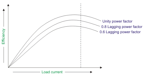
The maximum efficiency (ηmax) occurs when the variable losses equal to the constant losses. Since the copper loss is load dependent, hence it is a variable loss quantity. And the core loss is taken to be the constant quantity. So the condition for maximum efficiency is :
Now we can write maximum efficiency as :
|
|
|
 Power loss in the shunt circuit = VIsh (this includes the loss in the shunt regulating resistance).Mechanical losses = friction loss of bearings + friction loss at a commutator + windage loss.Core losses = hysteresis loss + eddy current lossStray loss = mechanical loss + core lossThe sum of the shunt field copper loss and stray losses may be considered as a combined fixed (constant) loss that does not vary with the load current I.
Therefore, the constant losses (in shunt and compound generators) = stray loss + shunt field copper losses.
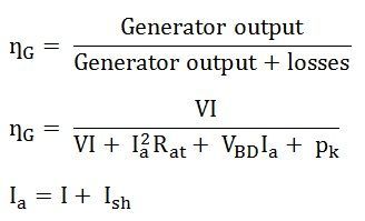
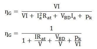
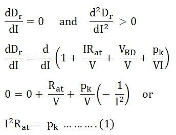
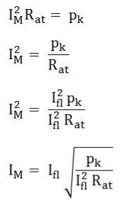
Generator efficiency is given by the equation shown below: If Ish is small compared with Ir, then Ia = I Therefore, The efficiency ȠG will be a maximum when the denominator Dr is a minimum. Where, Dr is minimum when Also,
Since d2Dr/dI2 is positive, the expression given by the equation (1) is a condition for the maximum value of Dr and the condition for the maximum value of efficiency.
|
|
|
|
|
|
|
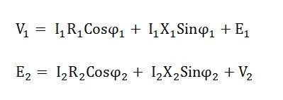
● The primary voltage of the transformer is always greater than the induced emf on the primary side. V1>E1
● The secondary terminal voltage at no load is always greater than the voltage at full load condition. E2>V2
By considering the above circuit diagram, the following equations are drawn
|
● These motors are used wherever stable speed is required.
● This kind of DC motor can be used in Centrifugal Pumps, Lifts, Weaving Machine, Lathe Machines, Blowers, Fans, Conveyors, Spinning machines, etc.
Thus, this is all about an overview of DC shunt motor. From the above information finally, we can conclude that these motors are ideal where exact speed control is needed due to their self-regulating speed capacities. The applications of this motor mainly comprise machines instruments like grinders, latches & industrial tools like compressors as well as fans.iii) d.c. series motor● It is a variable speed motor i.e. very low speed at high torqe and vice versa. However at no load motor tends to occupy dangerous speed. The motor has a very high starting torque. So it is used for :
○ The series DC motor is an industry workhorse for both high and low power, fixedandvariable speed electric drives.
○ Applications range from cheap toys to automotive applications.
○ They are inexpensive to manufacture and are used in variable speed household appliances such as sewing machines and power tools.
● Its high starting torque makes it particularly suitable for a wide range of traction applications.
● Industrial uses are hoists, cranes, trolly cars, conveyors, elevators, air compressors, vacuum cleaners, sewing machines etc.
Question. Why is parallel operation of transformers performed? Explain the complete laboratory procedure to perform the testIt is economical to installe numbers of smaller rated transformers in parallel than installing a bigger rated electrical power transformers. This has mainly the following advantages,2. To maximize electrical power system availability:
If numbers of transformers run in parallel, we can shutdown any one of them for maintenance purpose. Other parallel transformers in system will serve the load without total interruption of power.3. To maximize power system reliability:
If any one of the transformers run in parallel, is tripped due to fault of other parallel transformers is the system will share the load, hence power supply may not be interrupted if the shared loads do not make other transformers over loaded.4. To maximize electrical power system flexibility:
There is always a chance of increasing or decreasing future demand of power system. If it is predicted that power demand will be increased in future, there must be a provision of connecting transformers in system in parallel to fulfill the extra demand because, it is not economical from business point of view to install a bigger rated single transformer by forecasting the increased future demand as it is unnecessary investment of money. Again if future demand is decreased, transformers running in parallel can be removed from system to balance the capital investment and its return.
|
