Btech 5thSem Fluid Machinery
Q. 1 Choose the correct option form the following:
a. In hydraulic turbines.
- Inlet energy is greater than the outlet energy
- Outlet energy is greater than the inlet energy
- Inlet energy is equal to the outlet energy
- None of the above
Answer: Outlet energy is greater than the inlet energy
b. Which principle is used in Hydraulic Turbines?
- Faraday law
- Newton’s second law
- Charles law
- Braggs law
Answer: b) Newton’s second law
C. Which among the following is not a unit quantity of turbine?
- Unit speed
- Unit discharge
- Unit power
- Unit temperature
|
Answer: Unit temperature
d. The overall efficiency of a reaction turbine is the ratio of
- Actual work available at the turbine to the energy imparted to the wheel
- Work done on the wheel to the energy actually supplied to the turbine
- Power produced by turbine to the energy actually supplied by the turbine
- None
Answer: Power produced by turbine to the energy actually supplied by the turbine
e. The ratio of power at the shaft of turbine and power delivered by water to runner is known as?
- Mechanical efficiency
- Volumetric efficiency
- Hydraulic efficiency
- Overall efficiency
Answer: Mechanical efficiency
f. Among the following which turbine has least efficiency?
Pelton turbine
Kaplan turbine
Francis turbine
Propeller turbine
Answer: Pelton turbine
g. The hydraulic efficiency of Pelton turbine will be maximum when blade velocity is equal to _______
- V/2
- V/3
- V/4
- V/5
Answer: V/2
h. When the casing in a centrifugal pump decelerates the flow, what increases?
- Pressure
- Temperature
- Volume
- Flow rate
Answer: Pressure
I. Centrifugal pump works by imparting _______
- Potential energy
- Kinetic energy
- Heat energy
- Electrical energy
Answer: Kinetic energy
2. (a) A jet of water strikes with a velocity of 35 m/s a flat plate inclined at 30o with the axis of the jet. If the cross-sectional area of the jet is 25 cm2, determine ---
(i) the force exerted by the jet on the plate;
(ii) the components of the force in the direction normal to the jet;
(iii) the ratio in which the discharge gets divided after striking the plate.
Answer:
Given = Velocity = 35 m/s
The force exerted by the jet of water on a stationary plate is given by,
F=ρav2
= 1000 x 25 x 35 x 35
= 30.625 x 10³ N
Q. 3 a. Describe with neat sketch the working g of impulse turbine.
Answer:
Generally, Hydro turbines are classified into two groups based on how the energy is exchanged between the fluid and the turbine: impulse turbines and reaction turbines. Hydro turbines are installed to convert the potential energy and kinetic energy of water flow into mechanical work.
Impulse turbines operate based on the change of velocity vectors. In general, the potential energy of the water (or another fluid, e.g., steam) based on the height of the waterfall is converted into kinetic energy by one or more nozzles and then water hits the turbine blades at high speed causing the turbine to spin and consequently generates electricity. These turbines are more suitable for extracting energy from the high head and low flow conditions.
Working Principle of Impulse Turbine
In these turbines, the static pressure inside the runner is constant, and the turbine runner is at atmospheric pressure. The runner spins in the air, and the fluid is sprayed to the blades through the nozzle to exchange energy with the turbine. A jet nozzle or a series of nozzles directs the high-speed flow to the blades, which are usually in the shape of buckets or cups. Therefore, only pressure changes occur in the nozzles.
The application of the curved blades is to change the velocity of the flow. This strike causes a change in momentum and based on the law of conversation of energy, a force is applied to the turbine blades. According to Newton’s second law of motion, the force obtained through the motion of a fluid depends on two factors: the mass of the fluid entering the turbine and the changes in fluid velocity between the turbine inlet and outlet. Since no change in fluid mass occurs, only velocity changes are taken into account in calculating the force applied to the runner.
Thus, in the power generation process in impulse turbines, the following steps are implemented.
- The stored water flows from a source upstream through Penstock to be delivered to the nozzle.
- The potential energy of the water inside the nozzle is converted into kinetic energy and injected into the blades or buckets; thus, the runner spins.
- There is a mechanism to control the flow of water injected into the runner. The spear usually plays an important role in this process.
- The generator attached to the shaft converts mechanical energy into electrical energy.
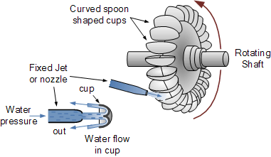
Fig. Schematic operation of an Impulse turbine
Impulse turbines have the ability to take all the kinetic energy from the water for high efficiency. Water is discharged into the atmosphere from the bottom of the turbine housing after reaching the runner; therefore, there is no suction at the bottom of the turbine. Here you can see schematically how an impulse turbine works in the process of extracting power from the kinetic energy of water as well as its components.
Components of an Impulse Turbine
Impulse turbines are composed of the following components.
Runner
The runner consists of a circular disk to which a number of curved blades are attached and a cylindrical shaft in the center. Shafts and runners are usually made of stainless steel. In cases where the flow head is less, the runner is made of cast iron.
Buckets
Buckets are a set of spoon-shaped cups that are mounted around the runner to exchange energy between the fluid and the turbine. The fluid jet hits these buckets after leaving the nozzle, making the turbine to rotate and exiting the outer edge of the bucket. The change in the direction of the fluid during the exit compared to the angle of impact varies depending on the design of the turbine.
To get the largest momentum, this angle must be 180 degrees. However, this angle is limited to angles of about 170 degrees due to considerations such as that the exit flow from one bucket does not collide with the next bucket and does not cause it to brake. These buckets are made of stainless steel or cast iron.
Nozzle
The nozzle is installed to adjust and jet the fluid flow to strike the buckets. As mentioned earlier, it is the only part of the impulse turbine assembly that the pressure changes and the flow head are converted into kinetic energy. The volume of water jet reaching the buckets is adjusted by a component called a spear, which is a conical needle that moves in and out of the nozzle by a hand wheel or automatically. By moving this needle backward, the water flow increases, and by moving forward, it decreases.
The nozzle is typically made from tungsten carbide, which is very hard and can withstand erosive particles.
Casing
The casing for an impulse turbine is a shield over the turbine to prevent the water from splashing and also to guide it to the spillway, which exists for the extra water to protect the structural integrity of the dam. Normally, Cast iron is used to manufacture the casing.
Penstock
Penstocks in hydropower plants are pipes and channels that carry water from dams and reservoirs to turbines. In general, they are made of steel. Water flows in these ducts under high pressures.
(b) A Pelton wheel, having a mean bucket diameter r.p.m. The net head o the Pelton wheel is 840 m. If the side clearance angle is 15o and discharge through the nozzle is 0.12 m3/s, determine
(i) power available at the nozzle, and
(ii) hydraulic efficiency of the turbine.
Answer:
If the side clearance angle is 15 degree and discharge through nozzle is 0.1m3/3
Find:
- Power available at the nozzle.
- Hydraulic efficiency of turbine.
Solutions:
Given:
1] Diameter of wheel, D = 1.2 m
2] Speed of wheel, N = 1000 r.p.m
∴ Tangential velocity of the wheel,


3] Net Head, H = 840m
4] Side clearance angle, θ=15 degree
5] Discharge, q=0.12m3/s
Velocity of jet at inlet,
v1=cv√2gH
=1×√2×9.81×840 [cv = 1.0]
v1 = 116.53 m/s
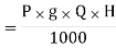
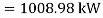
Step No. (1) Power available at the nozzle is given by

Step No (2) Hydraulic efficiency is given by
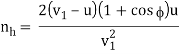
= 98.15%
Q.4 a. What is hydraulic turbine? How will you classify them?
Answer:
Hydraulic Turbines have a row of blades fitted to the rotating shaft or a rotating plate. Flowing liquid, mostly water, when pass through the Hydraulic Turbine it strikes the blades of the turbine and makes the shaft rotate. While flowing through the Hydraulic Turbine the velocity and pressure of the liquid reduce, these result in the development of torque and rotation of the turbine shaft. There are different forms of Hydraulic Turbines in use depending on the operational requirements. For every specific use a particular type of Hydraulic Turbine provides the optimum output.
The Hydraulic Turbines are classified according to the type of energy available at the inlet of the turbines, direction of flow, head at inlet of the turbine and specific speed of the turbines.
1] According to the type of energy at inlet.
a] Impulse turbine.
b] Reaction turbine.
2] According to the direction of flow through runner.
a] Tangential flow turbine.
b] Radial flow turbine.
c] Axial flow turbine.
d] Mixed flow turbine.
3] According to the head at inlet of turbine.
a] High head turbine.
b] Low head turbine.
4] According to the specific speed of the turbine.
a] Low specific speed turbine.
b] Medium specific speed turbine.
c] High specific speed turbine.
(b) In an inward flow reaction turbine, the head on the turbine is 32 m. The external and internal diameters are 1.43 m and 0.71 m respectively. The velocity of flow through the runner is constant and equal to 3.2 m/s. The guide blade angle is 10o and the runner vanes are rigid at inlet. If the discharge at outlet is radial, determine
(i) the speed of the turbine,
(ii) the vane angle at outlet of the runner and
(iii) hydraulic efficiency.
Answer:
Q.5 a. Explain briefly construction and working of Francis turbine?
Answer:
Francis Turbine is a combination of both impulse and reaction turbine, where the blades rotate using both reaction and impulse force of water flowing through them producing electricity more efficiently. Francis turbine is used for the production of electricity in hydro power stations. Majorly there are 2 turbines flow patterns on which they work, namely radial and axial flow concepts. An American civil engineer by name, James B. Francis in Lowell, Massachusetts comes up with an idea of combining both impulse and reaction turbine where water enters the turbine radically and exits axially. The working principle, main components and its application is discussed in this article.
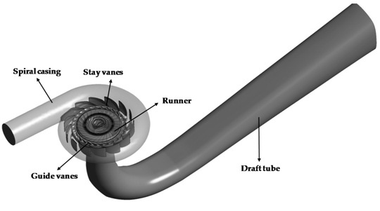
Construction of Francis Turbine
- Spiral Casing
- Guide Vanes
- Stay vanes
- Draft Tube
- Runner Blades
- Penstock
Spiral Casing
The spiral casing is the inlet medium for water supply to the turbine. This pipe allows passing the water flow from the dam or reservoir with high pressure. The turbine blades are arranged circularly, which means the water hitting the blades of the turbine must flow within the circular axis for efficient hitting. This is the reason to use spiral casing but because of the circular water movement, it loses its force. To keep the same force, the diameter of the casing will be gradually reduced.
Guide Vanes
These vanes are not immobile, but they transform their angle based on the requirement to control the hitting angle of water toward turbine blades to enhance efficiency. They also control the water flow rate into the runner blades so the power output is controlled for a turbine based on the load of the turbine.
Stay Vanes
Stay vane’s function is to guide the water flow toward the runner blades. These vanes stay motionless at their place & decrease the swirling of water because of radial flow. Once it enters the runner blades, then the turbine will become very efficient.
Draft Tube
The force at the outlet of the runner in the turbine is usually low as compared to atmospheric force. The water supply at the outlet cannot be discharged directly to the tailrace. So, a pipe or tube is used for water discharging from the outlet of the turbine toward the tailrace. This tube is known as Draft Tube where one finish of the tube is directly connected to the exit of the runner whereas another end is immersed under the water level within the tail-race.
Runner Blades
Runner blades are very essential components in this turbine. These are arranged at the center of the turbine where the water hits & the tangential power of the impact causes the shaft to turn for generating torque. These blades mainly include two parts where the lower half is designed in a small bucket shape to revolve the turbine with the help of the impulse action of the water supply. The upper half of the turbine blades utilize the reaction power of water supplied through it. So the runner turns through these two forces.
Penstock
Penstock plays a key role in transferring the water from the dam to the Francis turbine and it is made with cement or cast steel.
Francis Turbine Working
The water from the penstock enters into the spiral casing of the turbine, after that it flows through the guide vanes & stay vanes. The spiral case in the turbine is kept in decreasing diameter to maintain the pressure of water flow.
The stay vanes are motionless at their position to remove the spins from the water supply, which are produced because of the spiral casing & try to make the water flow more linear to be turned aside through changeable guide vanes.
The angle of guide vanes will decide the angle of the strike of water supply at the runner blades. The runner blades in the turbine are motionless & cannot change their position so the guide vanes control the turbine’s power output.
The turbine efficiency & performance mainly depends on the runner blades’ design. In this turbine, runner blades are mainly separated into two parts like the upper part and the lower part.
(b) A turbine is to operate under a head of 28 m at 200 r.p.m. The discharge and overall efficiency of the turbine are 8.5 m3/s and 89%, simultaneously. Determine
(i) specific speed of the turbine,
(ii) power generated and
(iii) types of turbine.
Answer:
Head on turbine H1=28m
Speed N1=200r.p.m
Discharge Q1=8.5m3/s
Overall efficiency No=89%
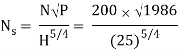
Specific speed = 
= 170.69
Since the specific speed lies in the range 50-250, the turbine is a Francis turbine.
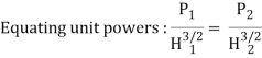
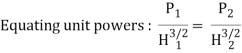
Since we are concerned with the same machine, we equate the relations for unit power.
Q.6 a. What is cavitation? How can it be avoided in reaction turbine?
Answer:
The formation of vapor bubbles in cavitation is not a major problem in itself but the collapse of these bubbles generates pressure waves, which can be of very high frequencies, causing damage to the machinery. The bubbles collapsing near the machine surface are more damaging and cause erosion on the surfaces called as cavitation erosion. The collapses of smaller bubbles create higher frequency waves than larger bubbles. So, smaller bubbles are more detrimental to the hydraulic machines.
Smaller bubbles may be more detrimental to the hydraulic machine body but they do not cause any significant reduction in the efficiency of the machine. With further decrease in static pressure more number of bubbles is formed and their size also increases. These bubbles coalesce with each other to form larger bubbles and eventually pockets of vapor. This disturbs the liquid flow and causes flow separation which reduces the machine performance sharply. Cavitation is an important factor to be considered while designing Hydraulic Turbines.
The formation, growth and collapse of vapour filled cavities or bubbles in a flowing liquid due to local fall in fluid pressure is called cavitation. The cavitation in a hydraulic machine affects in the following ways:
(a) It causes noise and vibration of various parts.
(b) It makes surface rough.
(c) It reduces the discharge of a turbine.
(d) It causes sudden drop in power output and efficiency.
The cavitation in reaction turbines can be avoided to a great extent by using the following methods:
(a) By installing the turbine below the tail race level.
(b) By using stainless steel runner of the turbine.
(c) By providing highly polished blades to the runner.
(d) By running the turbine runner to the designed speed.
(b) A turbine is to operate under a head of 23 m at 180 r.p.m. The discharge is 9 m3/s. If the overall efficiency is 90 percent, determine
(i) power generated,
(ii) specific speed of the turbine and
(iii) types of turbine.
Answer:
Power available at the turbine shaft,
P = wQH × ηo = (9810 × 9 × 23) × 0.9
= 1827.6 × 103 W
Specific speed,
= 159.44
Since the specific speed lies in the range 50-250, the turbine is a Francis turbine.
Since we are concerned with the same machine, we equate the relations for unit power.
= 1350 kW
Q.7 a. List the main component parts of centrifugal pump and explain briefly.
Answer:
Casing: The casing is the shell, cover or a housing, which protects and supports the components. In pumps, the casing it a crucial component for preventing leakage and sometimes retain pressure. Sometimes it is referred to as the snail shell.
There are two types of pump casings, volutes and diffusers. Although there are different varieties, both are designed to take energy in the form of velocity and convert it into pressure.
Volutes: Designed to capture the velocity of the liquid as it enters the outermost diameter of the impeller.
Diffusers: Diffusers have multiple vanes and are positioned so they begin close to the outer edge of the impeller.
Impellers: This is the rotating component in a centrifugal pump which is equipped with vanes or blades which rotate and move fluid within the pump. These are a crucial component of the pump as it converts energy derived from a source.
There are two types of impellers available, axial flow impeller and radial flow impeller. In an axel flow impeller, the fluid moves axially to the shaft, and are commonly used for high flow and very low-flow pressure applications. Whilst in a radial flow impeller the fluid moves perpendicularly to the shaft and are used in multi-stage split case centrifugal pumps.
Impellers are also classified based on their suction type, single suction and double suction. In a single suction impeller, liquid enters from the centre of the blades from only one direction. Whereas in a double suction impeller the liquid enters the centre of the impeller blades from both sides simultaneously.
Seals: Mechanical Seals and Gland Packings act as a method of containing fluid within the pump. They are installed within the ‘seal area’ or ‘stuffing box’. Gland packing is a rope-like material cut into rings to wrap around the shaft sleeve. A mechanical seal allows the rotating shaft to pass through a stationary housing. It allows the rotating shaft to ensure the ‘wet’ area of the pump, without allowing fluid to escape.
Gasket: Gaskets are a sealing element used where parts requiring sealing are in contact with each other and do not perform a relative movement.
O-Ring Seal: O-Ring closes a gap between two surfaces so liquids and gases cannot pass through in any direction. It changes its shapes when pressure is applied in the system.
Bearings: The Bearing reduces friction on moving parts within the pump and supports the shaft to rotate smoothly. They are commonly found in all pump types. There are multiple types of bearings available, including:
- Roller bearings: use a cylindrical shape roller between moving parts. These reduce the friction and support radial and axial load.
- Ball Bearings use balls to support the movement of parts, although simple in design they are suitable for high speeds and are easy to maintain.
- Babbitt bearings are a type of sleeve bearing that is coated in Babbit metal - and are commonly used in motors, pumps, turbine generators and fans.
- Sleeve bearings: appropriate for high speeds, these bearings are ideal for radial loads only and are designed to float.
- Pivot Shoe bearings: also known as Tilt Shoe Bearings or Kingsbury Bearings are suitable for axial load and are installed in high powered centrifugal pumps as a thrust bearing
Bearing pedestal: The bearing pedestal is sometimes referred to as a block or pillow block and is used to provide support for the rotating shaft. It is generally constructed of cast iron or cast steel.
Pressure Gauges: An instrument used to measure and display pressure levels. It monitors the pump’s discharge or inlet pressure.
Oil Seals: It prevents leakage or entry of oil from a chamber, usually fit around a rotating or reciprocating shaft.
(b) The impeller of a centrifugal pump has an external diameter of 500 mm and internal diameter of 220 mm and it runs at 1400 r.p.m. Assuming a constant radial flow through the impeller at 2.4 m/s and that the vanes at exit are set back at an angle of 22o, determine---
(i) the inlet vane angle;
(ii) the angle, absolute velocity of water at exit makes with the tangent;
(iii) the work done per N of water.
Answer:
Given:
D2=0.5m
D1=0.25m,
B2=0.05m
N=1200rpm,
Hm=48m,
Vf=Vf1=Vf2=3m/s ϕ=40∘
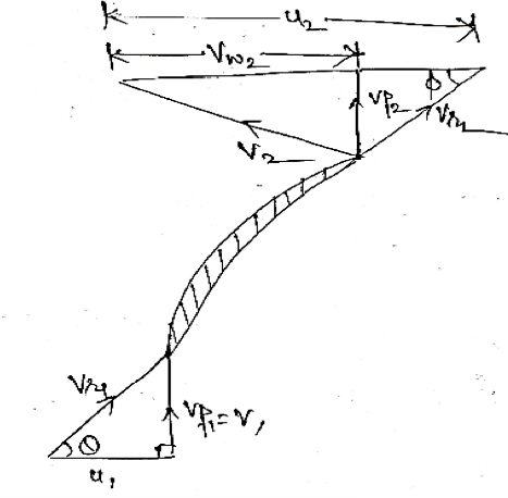
u1 = πD1N/60 = (π 0.25 1200)/60 = 15.7 m/s
u2 = πD2N/60 = (π 0.5 1200)/60 = 31.4 m/s
Q = πD2B2Vf2
= π 0.5 π 0.05 π 3
= 0.2355 m3/s
Vane angle at inlet,
Tan θ = Vη/u1 = 3/15.7 = 0.1911
θ = tan-1(0.1911) = 10.81o
Work done by impeller on water per sec,
W.D = W/g Vu2 . u2 = gQ/g V2 . u2
= (1000 9.81 0.2355)/9.81 Vu2 31.4
Tan = Vη/(u2 – Vu2 ) = 3/(31.4 - V2)
Tan 40 = 27.82 m/s
V2 = 27.82 m/s
WD = (1000 9.81 0.2355)/9.81 27.82 31.4
= 205720.55 Nm/s
Manometric efficiency: ηmano = gHm/V2. u2
= (9.81 48)/(27.82 31.4)
= 0.539 ≈ 53.9 %
8. (a) A centrifugal pump impeller has diameters at inlet and outlet as 350 mm and 720 mm respectively. The flow velocity at outlet is 2.5 m/s and the vanes are set back at an angle of 45o at the outlet. If the manometric efficiency is 70%, calculate the minimum starting speed of the pump.
Answer:
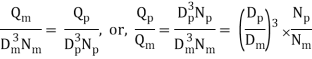
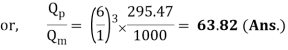
(b) In order to predict the performance of a large centrifugal pump, a scale model of one-sixth size was made with the following specifications:
Power P = 25 kW
Head Hmano = 7m
Speed N = 1000 r.p.m.
If the prototype pump has to work against a head of 22m, calculate its
(i) working speed,
(ii) the power required to drive it and
(iii) the ratio of the flow rates handled by the two pumps.
Answer:
Solution Scale ratio = one – sixth
Model: Prototype:
Power, Pm = 25 kW Power, Pp = ?
Head, (Hmano)m = 7 m Head, (Hmano)p = 22 m
Speed, Nm = 1000 r.p.m. Speed, Np = ?
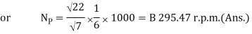
Speed of prototype, Np:
Power required to drive the prototype pump, Pp:
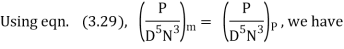
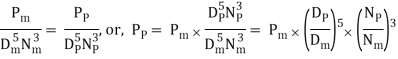
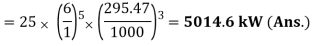
Ratio of the flow rates, QP/Qn :
Q. 9 a. What is reciprocating pump? Describe the principle and working of a reciprocating pump with a neat sketch. Why is reciprocating pump not coupled directly to the motor? Discuss the reason in detail?
Answer:
Reciprocating Pump is a Positive Displacement type pump that works on the principle of movement of the piston in forwarding and backward directions whereas the Centrifugal pump uses the kinetic energy of the impeller to supply the liquid from one place to another place.
- Water Sump
- Strainer
- Suction Pipe
- Suction Valve
- Cylinder
- Piston and Piston rod
- Crank and Connecting rod
- Delivery valve
- Delivery pipe
An Explanation for the parts of Reciprocating Pump:
The explanation for the parts of Reciprocating pump are as follows.
Water Sump:
It is the source of water. From the sump, water is to be transported to the delivery pipes by the usage of the piston.
Strainer:
It acts as a mesh that can screen all the dirt, dust particles, etc. from the sump. If there is no strainer, then the dirt or dust also enters into the cylinder which can jam the region and affects the working of the pump.
Suction Pipe:
The main function of the suction pipe is to collect the water from the sump and send it to the cylinder via a suction valve. The suction pipe connects the water sump and the cylinder.
Suction Valve:
It is a non-return valve which means it can take the fluid from the suction pipe and send it to the cylinder but cannot reverse the water back to it. In the sense, the flow is unidirectional.
This valve opens only during the suction of fluid and closes when there is a discharge of fluid to outside.
Cylinder:
It is a hollow cylinder made of cast iron or steel alloy and it consists of the arrangement of piston and piston rod.
Piston and Piston rod:
For suction, the piston moves back inside the cylinder and for discharging of fluid, the piston moves in the forward direction.
The Piston rod helps the piston to move in a linear direction i.e. either the forward or the backward directions.
Crank and Connecting rod:
For rotation, the crank is connected to the power source like engine, motor, etc. whereas the connecting rod acts as an intermediate between the crank and piston for the conversion of rotary motion into linear motion.
Delivery Pipe:
The function of the delivery pipe is to deliver the water to the desired location from the cylinder.
Delivery valve:
Similar to the suction valve, a delivery valve is also a Non-return valve. During suction, the delivery valve closes because the suction valve is in opening condition and during Discharge, the suction valve is closed and the delivery valve Is opened to transfer the fluid.
These are the various components of Reciprocating pump. Let’s understand the working principle of it.
Working Principle of Reciprocating Pump:
When the power supply is given to the reciprocating pump, the crank rotates through an electric motor.
The angle made by the crank is responsible for the movement of the piston inside the cylinder. By referring to the above diagram, the piston moves towards the extreme left of the cylinder when the crank meets position A i.e. θ=0.
Similarly, the piston moves towards the extreme right of the cylinder when the crank meets the position C i.e. θ=180.
A partial vacuum in the cylinder takes place when the piston movement is towards the right extreme position i.e. (θ=0 to θ=180.) and that makes the liquid enter into the suction pipe.
This is due to the presence of atmospheric pressure on the sump liquid which is quite less than the pressure inside the cylinder. Therefore, due to the difference in pressure, the water enters into the cylinder through a non-return valve.
The water which stays in the volume of the cylinder has to be sent to the discharge pipe via discharge valve and this can be done when the crank is rotating from C to A i.e. (θ=180 to θ=360) which moves the piston in the forward direction.
Due to the movement of the piston in a forward direction, the pressure increases inside the cylinder which is greater than the atmospheric pressure.
This results in the opening of the delivery valve and closing of the suction valve.
Once the water comes into the delivery valve, it cannot move back to the cylinder because it is a unidirectional valve or non-return valve.
From there, it enters into the delivery pipe so that it can be sent to the required position.
Therefore, in this way, the water is sucked and discharged from the sump to the desired location through the piston inside the cylinder.
- A reciprocating pump is basically a piston in a cylinder with two check valves in ports in front of the piston.
- When the piston is moving back in the cylinder, a check valve allows fluid to fill the cylinder from the intake port, while the discharge port is blocked by its check valve.
- When the piston goes back the other way, the check valve in the discharge port allows fluid to pass while the check valve in the intake port closes.
- In case of emergency, if the cylinder stops, the motor does not. So it can be harmful for motor. Designers couple the high power motor to the cylinder of pump by means of a clutch. So the motor can continue to rotate while the cylinder stops.
- Also in case of closing the outlet valve of a pump, the pressure in the cylinder can fail the cylinder or crankshaft and accessories. In this case the clutch can separate the power from motor to the pump and prevent failure of pump.
b. What is negative slip in reciprocating pump? Explain with neat sketches the function of air vessels in a reciprocating pump.
Answer:
As we have discussed above that slip in reciprocating pump is basically the difference between the theoretical discharge and actual discharge of the reciprocating pump. If actual discharge is more than the theoretical discharge, slip of the reciprocating pump will be negative and it could be concluded by considering the equation of slip of reciprocating pump.
Negative slip will occur when suction pipe is long, delivery pipe is short and pump is running at high speed.
So, we have seen briefly describe the reciprocating pump and basically we have discussed here the slip and negative slip in reciprocating pump.
An air vessel is basically a closed chamber from its one side which will have compressed air in the top and water or liquid at the bottom of the chamber. At the base of the chamber, there will be an opening through which liquid may flow in to the air vessel or out from the air vessel.
Air vessels will be installed at suction side and delivery side of the reciprocating pump as displayed here in following figure.
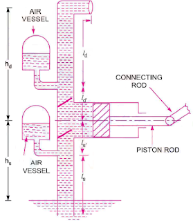
These air vessels will be installed as close as possible with the cylinder of the reciprocating pump.
Air vessel is installed with reciprocating pump in order to secure the following task.
- To secure the continuous flow of liquid with uniform rate of flow
- To save the suction and discharge pipe
- To save the considerable amount of work in overcoming the frictional resistance in the suction and delivery pipes
- To run the reciprocating pump at a high speed without separation
Air vessel acts on the same principle on the basis of which hydraulic accumulator and flywheel work. It stores energy when there will be availability of additional energy and it releases the energy when it is required.
Air vessel stores and releases additional energy with the help of compressed air contained in the top of the chamber of air vessel.
When liquid will flow in to the vessel, air containing at the top of the chamber of air vessel will be compressed and when liquid will flow out from the vessel, air containing at the top of the chamber of air vessel will be expanded.


